Power transformers are critical components in modern power systems. They enable the efficient transmission and distribution of electricity by stepping up or stepping down voltage levels. But where exactly are these devices used? From power stations to local neighborhoods, power transformers are at the heart of the energy flow, quietly supporting modern life.
Where Are Power Transformers Used in the Power Grid?

The electrical power grid is a complex, multi-tiered infrastructure that enables the generation, transmission, and distribution of electricity from power plants to consumers. A key enabler at every level of this network is the power transformer. Without them, it would be impossible to move electricity efficiently or safely across vast distances and diverse voltage requirements.
Power transformers are used throughout the power grid—at generation plants to step up voltage for transmission, at high-voltage substations to interconnect or step down voltage levels, in regional substations to prepare power for distribution, and finally near consumers to deliver electricity at usable voltages. Each stage relies on transformers to match voltage to grid segment needs and maintain system reliability.
This article explains where and why power transformers are used across different stages of the power grid, helping utilities, engineers, and decision-makers optimize infrastructure and ensure uninterrupted power flow.
Power transformers are used throughout the power grid, from generation to distribution substations, for voltage regulation and system efficiency.True
Transformers allow electricity to be stepped up for transmission and stepped down for safe delivery, ensuring grid performance and safety.
Power transformers are only used in generation plants and have no role in transmission or distribution.False
Power transformers are essential at all levels of the grid for voltage adaptation and fault isolation.
1. Generation Plants (Step-Up Transformers)
| Function | Step-up Voltage for Transmission |
|---|---|
| Input voltage | 11 kV – 25 kV (generator output) |
| Output voltage | 132 kV – 400/765 kV (grid level) |
| Transformer Type | Step-up power transformer |
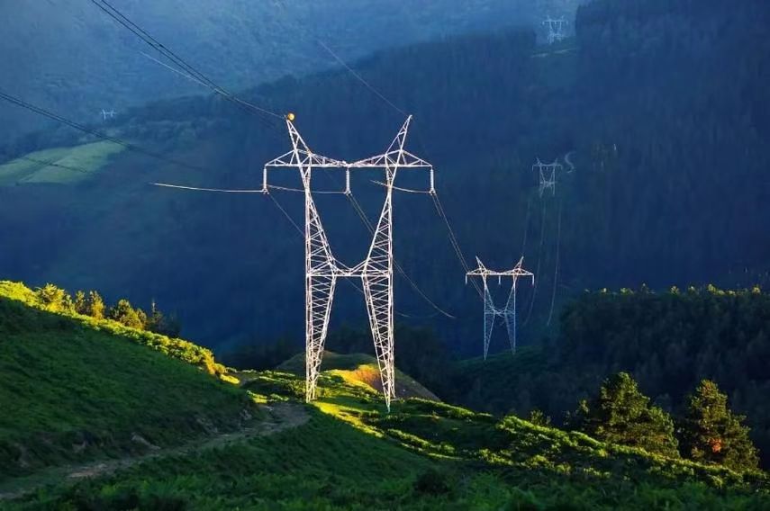
At the point of generation, power is produced at a relatively low voltage. A step-up transformer raises the voltage to transmission levels to reduce current and minimize I²R losses over long distances.
These are typically large oil-immersed transformers located in the switchyard of a power station.
2. High-Voltage Transmission Substations
| Function | Interconnect Regions or Transmission Levels |
|---|---|
| Voltage Levels | 400 kV ↔ 220 kV ↔ 132 kV |
| Transformer Type | Power transformer or autotransformer |
Transmission substations use power transformers to interconnect different parts of the high-voltage grid, enabling power flow between regions, utilities, and states. They also allow voltage regulation and reactive power management.
These transformers are strategically located at regional or national grid nodes.
3. Receiving Substations (Step-Down Transformers)
| Function | Reduce Voltage for Distribution Entry |
|---|---|
| Voltage Input | 132 kV – 220 kV |
| Voltage Output | 33 kV – 66 kV |
| Transformer Type | Step-down transformer |
These substations serve as the transition point from high-voltage transmission to medium-voltage distribution. Transformers here step down voltage and protect the grid from faults with circuit breakers and relays.
Often found near cities, industrial hubs, or large substations.
4. Primary Distribution Substations
| Function | Prepare Voltage for Local Grids |
|---|---|
| Voltage Range | 33 kV → 11 kV (typical) |
| Transformer Type | Distribution class power transformer |
These stations feed secondary distribution networks, powering residential, commercial, and small industrial zones.
Transformers are compact yet robust, with high reliability and frequent use of OLTC (on-load tap changers) for voltage regulation.
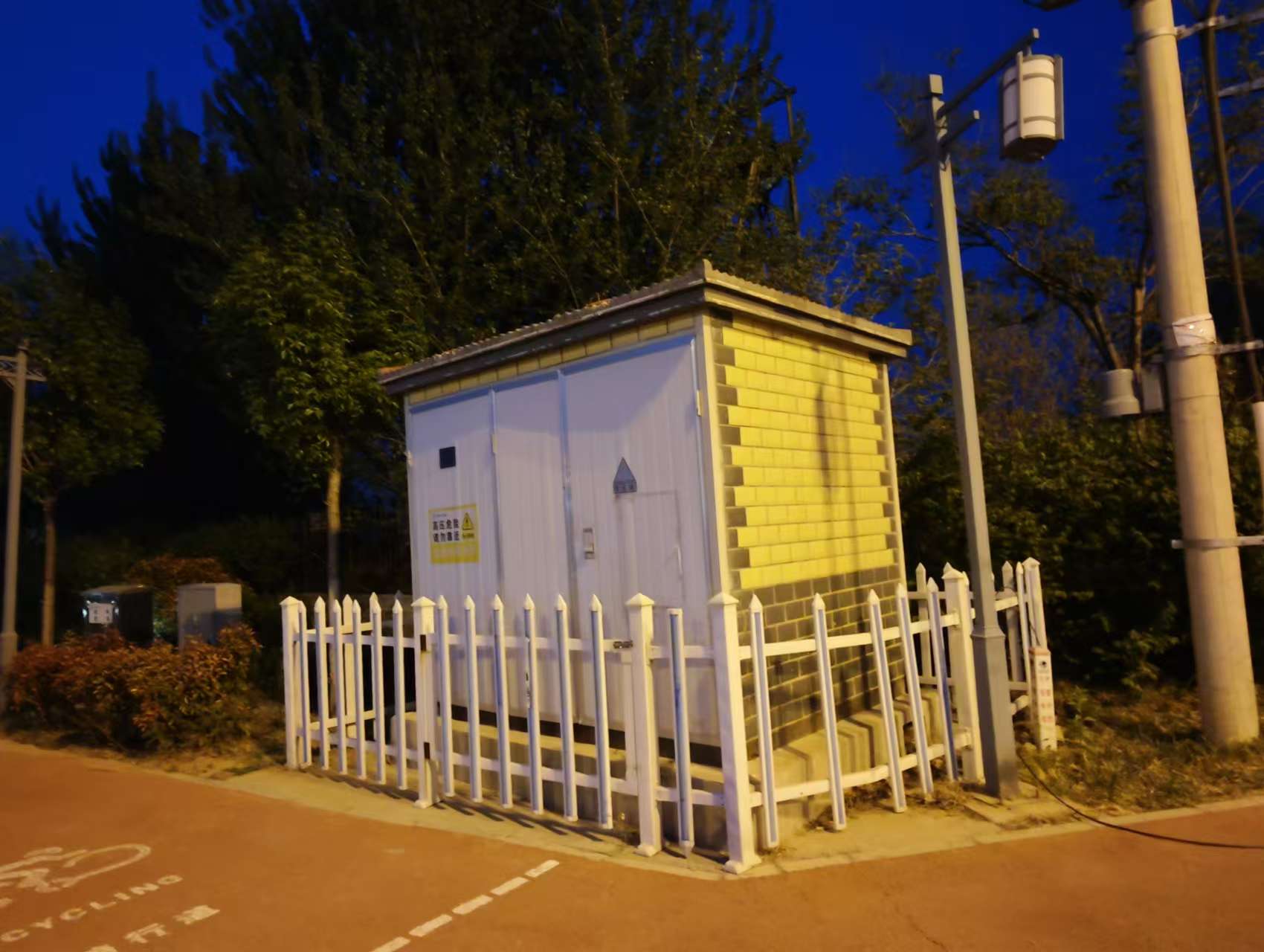
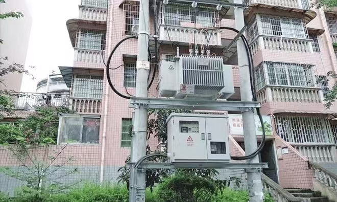
5. Secondary Distribution Transformers (Pole-Mounted or Pad-Mounted)
| Function | Final Step-Down for End-Users |
|---|---|
| Input voltage | 11 kV (or 6.6 kV, 33 kV depending on region) |
| Output voltage | 400 V / 230 V |
| Transformer Type | Distribution transformer |
These are the most common transformers seen in urban and rural neighborhoods, providing safe voltage for household and small commercial use.
Found on poles, sidewalks, or building basements—depending on urban design.
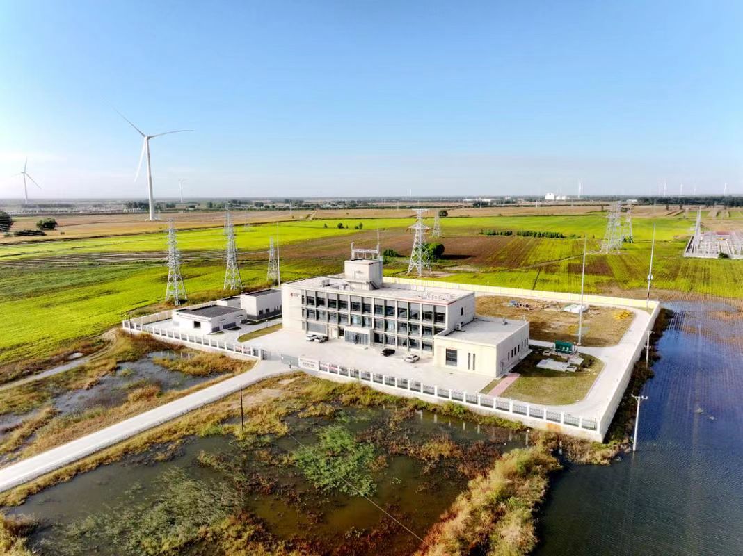
6. Renewable Energy Collector Substations
| Function | Export Renewable Power to the Grid |
|---|---|
| Input voltage | 400/690 V (wind, solar output) |
| Output voltage | 11 kV – 33 kV |
| Transformer Type | Step-up pad-mounted or skid transformer |
Renewables like wind turbines and solar panels generate power at low voltages. Step-up transformers are used to raise this to medium voltage, which is then sent to substations or fed into the grid.
Typically installed at each turbine base or solar inverter cluster.
7. Industrial Plants and Large Facilities
| Function | Power Equipment and Internal Systems |
|---|---|
| Voltage Levels | 33/11/6.6 kV → 400/230 V |
| Transformer Type | Power transformer, dry-type, or VPI type |
Industrial transformers serve machinery, HVAC, automation panels, and protection systems, often operating within private grids or microgrids.
Located in plant rooms, electrical basements, or perimeter power yards.
Summary Table: Where Power Transformers Are Used in the Grid
| Grid Segment | Transformer Function | Voltage Conversion |
|---|---|---|
| Generation Plant | Step-up for transmission | 11–25 kV → 132–765 kV |
| Transmission Substation | Grid interconnection | 132 ↔ 220 ↔ 400 kV |
| Receiving Substation | Step-down for distribution | 400/220/132 kV → 66/33 kV |
| Primary Distribution Substation | Local network voltage control | 33 kV → 11 kV |
| End-user Distribution Transformer | Final voltage step-down | 11 kV → 400/230 V |
| Renewable Collector Substation | Integrate renewable sources | 400–690 V → 11/33 kV |
| Industrial or Commercial Facility | Power internal loads | 6.6/11/33 kV → 415/230 V |
How Are Transformers Used in Power Plants?
Modern power plants are technological marvels, capable of generating hundreds or thousands of megawatts—but without transformers, none of this power would make it to the grid. A common yet critical challenge in power generation is the mismatch between the voltage level generated and the voltage needed for transmission. When this mismatch isn't managed, it leads to serious consequences: high transmission losses, overloading, insulation breakdown, and catastrophic equipment failure. Transformers are the engineering solution to this problem. They allow power to be stepped up to high voltages for efficient transport across the grid and stepped down again for local distribution, forming the backbone of modern power delivery systems. In this article, we’ll explore how different types of transformers are integrated into power plants and how they ensure that the electricity generated reaches consumers reliably, efficiently, and safely.
Transformers in power plants are essential devices that convert the low-voltage output of generators (typically 11–25 kV) into high voltages (132–765 kV) suitable for long-distance transmission. This is done through generator step-up transformers (GSUs). Additional auxiliary and station service transformers support internal operations by stepping down voltage for plant equipment and controls. Each transformer type plays a specific role in enabling efficient, stable, and scalable energy delivery.
Understanding the role of transformers in power plants not only helps you design more efficient systems but also helps avoid downtime, equipment degradation, and costly energy losses. Read on to explore transformer functions, design parameters, and use cases inside a power generation facility.
Power plants use generator step-up transformers to raise voltage from the generator to transmission levels.True
Generators typically produce electricity at low voltages (11–25 kV), which is increased to 132–765 kV for efficient long-distance transmission.
Auxiliary transformers in power plants are responsible for sending electricity to the national grid.False
Auxiliary transformers supply internal plant loads, while generator step-up transformers connect to the grid.
Generator Step-Up Transformers (GSU): The First Link to the Grid
| Function | Voltage Conversion | Typical Ratings | Location |
|---|---|---|---|
| Raise voltage for transmission | 11–25 kV → 132–765 kV | 200 MVA – 1500 MVA | Between generator and switchyard |
Generator step-up transformers (GSUs) are the most critical transformer units in any power plant. They are responsible for converting the generated low voltage into high-voltage electricity suitable for transmission. These transformers are built with robust insulation, on-load tap changers (OLTCs), and advanced cooling systems (ONAN, ONAF, OFAF, OFWF) to handle extreme operational loads and fault conditions. Because of the massive power they handle, GSUs are usually three-phase oil-immersed transformers equipped with bushings designed for high voltage stress.
These transformers must also handle:
- Harmonic suppression due to generator operations.
- Short-circuit withstand capability.
- Synchronization compatibility with the national grid frequency.
Auxiliary and Station Service Transformers: Powering Internal Operations
| Purpose | Voltage Conversion | Typical Loads Supplied |
|---|---|---|
| Power plant internal systems | 132–33 kV → 6.6/3.3/0.415 kV | Pumps, HVAC, lighting, controls, cooling fans |
While the GSU transformer handles grid connectivity, auxiliary transformers are used to step down voltage from the high-voltage bus to medium and low voltage levels needed for the plant’s internal operations. These include drives, conveyor systems, feedwater pumps, cooling tower fans, and DCS (distributed control system) panels.
Many plants use unit auxiliary transformers (UATs) connected to the generator terminals and station service transformers (SSTs) connected to the grid. This ensures that internal power is always available—even if one source fails.
Protection, Control, and Monitoring of Transformers
| System | Purpose | Common Technologies |
|---|---|---|
| Differential Protection | Detects internal faults within the transformer | Current transformers (CTs), protective relays |
| Buchholz Relay | Gas accumulation detection in oil tanks | Oil-immersed transformer safety feature |
| OLTC Monitoring | Ensures proper voltage regulation | Tap position sensors, SCADA feedback loops |
| Cooling System Control | Prevents overheating | Forced oil/water cooling with thermostats |
Transformers in power plants are equipped with advanced protection and diagnostic systems to prevent faults and ensure operational stability. Modern transformers include IoT-enabled sensors and connect to SCADA systems for real-time performance tracking.
Case Study: Transformer Integration in a 500 MW Thermal Power Plant
| Component | Transformer Type | Specifications |
|---|---|---|
| Generator Output | Generator Step-Up Transformer | 500 MVA, 22 kV/400 kV, ONAN/ONAF cooling |
| Auxiliary Systems | Unit Auxiliary Transformer | 50 MVA, 22 kV/6.6 kV |
| Emergency Systems | Station Transformer | 20 MVA, 400 kV/6.6 kV |
This example shows the diverse transformer setup in a thermal power station, with dedicated transformers for grid export, auxiliary functions, and standby operations. Engineering teams must calculate MVA ratings based on load forecasts, short-circuit levels, and operational redundancy.
Diagram: Transformer Roles in a Power Plant
| Stage | Voltage Level | Transformer Role |
|---|---|---|
| Generator Output | 11–25 kV | Generator Step-Up Transformer (GSU) |
| Grid Interface | 132–765 kV | GSU + Switchyard |
| Internal Equipment | 3.3–6.6 kV / 415 V | Auxiliary and Station Service Transformers |
| Emergency Backup | 6.6 kV | Diesel Generator + Step-down Transformer |
What Is the Role of Transformers in Substations?
Substations are critical nodes in the electrical power grid, but their operation would be impossible without transformers. A widespread issue in poorly designed or aging substations is voltage mismatch—either delivering too much voltage that risks damaging equipment or too little that causes power losses, inefficiencies, or service interruptions. This creates costly consequences for utilities and end-users alike. Fortunately, transformers solve these problems by adapting voltage levels between different stages of the grid. Whether stepping down high voltages for safe distribution or stepping up for regional transmission, transformers ensure that power flows efficiently and safely at every node in the system.
Transformers in substations regulate voltage levels between transmission and distribution systems. They step down high-voltage electricity from the transmission grid to lower voltages suitable for industrial, commercial, or residential distribution. In some substations, transformers also step up voltage levels to move power efficiently between grid zones. Their primary role is voltage adaptation, grid balancing, and system protection.
If you want your power infrastructure to be stable, efficient, and capable of meeting growing energy demands, you must understand how transformers operate within substations. This article provides a comprehensive look at the types of transformers used, their configurations, protection systems, and how they support reliable grid operations.
Transformers in substations are primarily used for voltage transformation between transmission and distribution systems.True
Substation transformers convert high-voltage power from transmission lines into usable lower voltages for distribution.
Substations deliver power directly from generators to consumers without transformers.False
Substations require transformers to adjust voltage levels and safely deliver electricity through the grid.
Types of Transformers Used in Substations
| Transformer Type | Primary Function | Typical Voltage Range |
|---|---|---|
| Power Transformers | Step down transmission voltage | 132 kV → 33/11 kV |
| Distribution Transformers | Final step-down before customer delivery | 11 kV → 400 V |
| Autotransformers | Interconnect similar transmission voltages | 400 kV ↔ 220 kV |
| Instrument Transformers | Voltage and current measurement for protection | Various (Low-power sensing range) |
Substation transformers vary based on their voltage class, load demand, and role within the grid. Below, we examine these in detail.
1. Power Transformers: Voltage Adaptation at Bulk Level
| Feature | Specification |
|---|---|
| Voltage Ratio | 400/220/132 kV → 33/11 kV |
| Rated Capacity | 50 MVA – 1,000+ MVA |
| Cooling System | ONAN, ONAF, OFAF, OFWF |
| Applications | Transmission-to-distribution interface |
Power transformers are the heart of high-voltage substations. They are responsible for adapting bulk transmission voltages (e.g., 400 kV) into medium voltage levels used by regional grids. These transformers are typically three-phase, oil-immersed units with high thermal endurance and often include on-load tap changers (OLTC) to dynamically adjust voltage under load.
2. Distribution Transformers: The Last Step Before Load
| Function | Step-down for customer supply |
|---|---|
| Voltage Conversion | 11 kV → 400/230 V |
| Installation Types | Pole-mounted, pad-mounted |
| Capacity | 25–2,500 kVA |
| Features | Compact, sealed, low-loss design |
These transformers are located at secondary substations or near consumer zones, delivering power to neighborhoods and businesses. Often pole-mounted in rural areas or pad-mounted in urban zones, they must be efficient, quiet, and low-maintenance.
3. Autotransformers: Regional Interconnection
| Purpose | Voltage linking between grid zones |
|---|---|
| Voltage Ratio | 400 kV ↔ 220 kV ↔ 132 kV |
| Cost Advantage | Fewer windings, lighter design |
| Risk Factor | Less isolation—needs better protection |
Autotransformers are common in large transmission substations, enabling power flow between zones operating at similar voltage levels. Their compact design saves material but requires advanced protection systems due to shared windings.
4. Instrument Transformers: For Monitoring and Protection
| CT/PT Function | Convert high power to measurable range |
|---|---|
| Current Transformers (CTs) | High current → standard 5 A/1 A signal |
| Voltage Transformers (VTs or PTs) | High voltage → 110 V reference |
| Purpose | Relay activation, SCADA, metering |
Though not involved in voltage transformation for transmission or distribution, instrument transformers provide accurate electrical measurements and isolation, which is critical for protection relays and automated control systems.
Key Roles of Transformers in Substations
| Function | Explanation |
|---|---|
| Voltage Step-down | Converts transmission-level voltage to distribution level for downstream delivery |
| Grid Interconnection | Balances power flow between grid segments with different voltage ratings |
| Load Isolation | Separates faulty sections using transformer zones and protection schemes |
| Voltage Regulation | Maintains steady voltage levels using OLTCs and tap changers |
| Grounding & Fault Management | Neutral grounding transformers ensure system stability during faults |
Substation Configuration Example
Let’s take a 220/132/33 kV AIS substation example:
| Stage | Transformer Type | Voltage Conversion | Purpose |
|---|---|---|---|
| Incoming Transmission | Power Transformer | 220 kV → 132 kV | Feeds regional network |
| Secondary Bus | Power Transformer | 132 kV → 33 kV | Feeds primary distribution substations |
| Distribution Node | Distribution Transformer | 33 kV → 11 kV or 400 V | Final delivery to industrial/residential |
Such substations ensure voltage control, fault isolation, and power quality regulation across multi-voltage levels.
Monitoring & Protection Systems in Substation Transformers
| System | Function | Components |
|---|---|---|
| Differential Protection | Detects internal transformer faults | CTs, Relays |
| OLTC Monitoring | Manages tap positions for voltage regulation | Tap position sensors, SCADA |
| Buchholz Relay | Detects gas from internal arcing | Gas relay, alarm triggers |
| Thermal Monitoring | Prevents overheating and aging | RTDs, Oil temperature sensors |
Are Power Transformers Used in Industrial Settings?
In industrial zones, where power demand is large and fluctuating, unstable voltage or poorly matched transformer systems can result in serious consequences—production downtime, equipment failure, electrical fires, and increased operating costs. One of the key solutions to these challenges is the use of power transformers specifically engineered for industrial settings. These transformers ensure that electrical energy is delivered at the right voltage and capacity to power heavy-duty equipment, lighting systems, motors, automation units, and even internal microgrids. This article reveals how industrial power transformers work, where they are used, and why they are essential to the backbone of high-performance manufacturing and industrial operations.
Yes, power transformers are widely used in industrial settings to step down medium- or high-voltage electricity from utility grids to lower voltages required by industrial equipment. These transformers ensure voltage compatibility, system stability, and electrical safety for machines, control systems, and internal power distribution networks within factories and large facilities.
If you want to ensure that your factory or industrial site runs with high reliability and energy efficiency, understanding how to integrate the right power transformer is essential. Below, we explore their roles, types, technical parameters, and real-world deployment practices in industrial infrastructure.
Power transformers are commonly used in industrial plants to manage voltage levels from the utility grid.True
Industrial transformers step down medium or high voltage to levels required for factory systems, ensuring operational reliability and equipment safety.
Only small transformers are used in industries since power demand is low.False
Industries often require medium to large power transformers due to high power consumption and sensitive electrical loads.
Key Roles of Power Transformers in Industrial Applications
| Function | Description |
|---|---|
| Voltage Transformation | Converts grid supply voltage (e.g. 33kV or 11kV) to usable plant voltage levels (e.g. 415V, 690V) |
| Power Supply to Equipment | Feeds CNC machines, motors, HVAC systems, compressors, and heavy production lines |
| Load Management & Protection | Isolates equipment from surges, harmonics, and voltage fluctuations |
| Internal Distribution Network Support | Feeds local switchboards, sub-distribution panels, and critical process control zones |
Common Types of Power Transformers in Industrial Facilities
| Transformer Type | Usage | Voltage Range |
|---|---|---|
| Oil-Immersed Power Transformer | Main power intake from the grid | 33kV / 11kV → 415V / 690V |
| Dry-Type Transformer | Indoor service for sensitive or critical loads | 6.6kV / 3.3kV / 690V → 400V |
| VPI (Vacuum Pressure Impregnated) | For humid/dusty environments, often modular | 11kV → 0.415kV |
| Rectifier Transformer | Industrial DC drives, electroplating, smelters, furnaces | Custom 3-phase AC to DC systems |
Each of these transformer types is selected based on factors like environmental conditions, voltage class, installation type (indoor vs outdoor), and criticality of the load.
Technical Parameters & Design Considerations
| Design Factor | Typical Industrial Standard |
|---|---|
| Rated Power | 100 kVA to 20 MVA (depending on load demand) |
| Voltage Class | 6.6kV / 11kV / 22kV / 33kV primary, 415V / 690V secondary |
| Cooling Type | AN (Air Natural), AF, ONAN, ONAF |
| Protection Devices | Buchholz relay, differential protection, surge arrestors |
| Mounting Type | Pad-mounted, skid-mounted, pole-mounted |
| Standards Compliance | IEC 60076, ANSI C57, IS 2026 |
Most modern industrial transformers also include tap changers, SCADA-compatible sensors, and insulation grade customization based on the application (Class F, H, etc.).
Real-World Layout Example: Large-Scale Manufacturing Plant
| Component | Transformer Role | Voltage Conversion |
|---|---|---|
| Main Incoming Transformer | Receives power from utility grid | 33 kV → 11 kV |
| Plant Power Transformer | Distributes to production zones | 11 kV → 690 V |
| Motor Control Center (MCC) Supply | Feeds large motors | 690 V → 400 V |
| Automation Control Transformer | Powers PLCs, sensors, instrumentation | 400 V → 110 V / 24 V |
This setup ensures energy separation, safety isolation, and process reliability, especially in sectors like steel, cement, pharmaceuticals, and data centers.
Industry-Specific Use Cases
| Industry | Power Transformer Role |
|---|---|
| Textile | Drive looms, HVAC systems, compressors |
| Automotive | Robotic arms, painting lines, welding equipment |
| Mining | Crusher motors, conveyors, underground pumps |
| Oil & Gas | Hazardous area rated transformers for rigs and processing units |
| Food Processing | Packaging machines, controlled environment systems |
These use cases often require custom-designed transformers to match power factors, reactive power compensation, and harmonic filtering needs.
Advantages of Using Industrial Power Transformers
| Advantage | Explanation |
|---|---|
| Improved Energy Efficiency | Minimizes losses by closely matching voltage needs to equipment |
| Enhanced Equipment Lifespan | Protects against overvoltage, harmonics, and electrical noise |
| Load Balancing | Allows isolation and control of plant zones or processes |
| Flexibility for Expansion | Easily scaled with additional capacity or parallel installations |
| Safety and Compliance | Meets national and international electrical codes and standards |
How Do Urban and Rural Areas Use Transformers Differently?
Power delivery challenges vary drastically between urban cities and remote rural villages. In urban areas, transformer systems must accommodate high-density loads, underground cabling, and limited space, while rural settings face issues like long distribution lines, low population density, and exposure to environmental elements. Failing to use the right type of transformer in each environment can lead to overloads, voltage drops, high line losses, and frequent outages. By customizing transformer design, installation, and capacity for each setting, utilities can ensure efficient, reliable, and scalable electricity access. This article will explore the key differences in how transformers are used in urban and rural grids, providing real-world data, system design insights, and usage strategies.
Urban areas use pad-mounted or substation transformers for compact, high-load, underground power distribution, whereas rural areas use pole-mounted transformers optimized for long-distance, low-density overhead delivery. Each setting demands tailored transformer capacity, cooling methods, mounting styles, and voltage regulation techniques based on grid infrastructure, consumer type, and environmental constraints.
Understanding the differences between urban and rural transformer deployment helps utility engineers and infrastructure planners deliver optimized power systems, reduce energy loss, and enhance service continuity across diverse communities.
Urban transformers are typically pad-mounted or substation-based to serve high-density, underground cable networks.True
Urban areas require compact, secure transformers to match underground grid systems and limited installation space.
Rural transformers are primarily used for underground cable systems.False
Rural areas mostly rely on overhead lines, with pole-mounted transformers suited for long spans and fewer consumers.
Transformer Design and Installation: Urban vs Rural
| Feature | Urban Area | Rural Area |
|---|---|---|
| Transformer Type | Pad-mounted, dry-type, kiosk, substation units | Pole-mounted oil-filled transformers |
| Mounting Style | Ground-level in enclosures or utility basements | Mounted on distribution poles |
| Cooling Method | Air-cooled (AN), dry-type, forced ventilation | Oil-cooled, natural convection (ONAN) |
| Location | Inside kiosks, buildings, substations | Along roadside or field poles |
| Access & Maintenance | Underground cable access, sealed environments | Exposed, requiring aerial bucket maintenance |
Voltage and Capacity Differences
| Parameter | Urban Distribution | Rural Distribution |
|---|---|---|
| Incoming Supply Voltage | 11 kV or 33 kV | 11 kV (or sometimes 6.6 kV) |
| Output Voltage | 400/230 V three-phase | 230 V single-phase or 400 V three-phase |
| Transformer Capacity | 315–2,500 kVA | 25–200 kVA |
| Load Type | Mixed (residential, commercial, EVs, etc.) | Predominantly residential and agricultural |
| Load Density | High | Low |
Urban grids must support denser, more diverse loads, including high-rise buildings, electric vehicle charging, and commercial operations. Transformers are thus larger, better cooled, and often modular. In contrast, rural transformers supply fewer consumers, often spread out over long distances, leading to smaller capacities and longer feeder lines.
Installation and Protection Strategies
| Aspect | Urban System | Rural System |
|---|---|---|
| Protection Devices | Circuit breakers, surge arresters, OLTCs | Drop-out fuses, surge arresters |
| Redundancy | N+1 or dual-feed configurations | Radial single-feed systems |
| Voltage Regulation | Smart tap changers, SCADA control, capacitor banks | Line regulators, step voltage regulators |
| Network Topology | Loop or ring-fed LV networks | Radial distribution lines |
Urban transformers are often equipped with advanced monitoring and voltage control systems, enabling load balancing, energy metering, and remote diagnostics via SCADA. Rural areas may rely on simpler, manual systems with basic voltage regulation equipment and limited automation due to cost and infrastructure constraints.
Environmental and Security Considerations
| Factor | Urban Transformers | Rural Transformers |
|---|---|---|
| Security Needs | High—located in enclosures to prevent tampering | Moderate—mounted on poles with visible access |
| Environmental Exposure | Low—protected from weather and vandalism | High—subject to lightning, wind, and animals |
| Visual Aesthetics | Important—often hidden in landscape designs | Less priority—visibility acceptable |
| Maintenance Access | Difficult—requires confined space tools | Easier—accessible via truck or lift |
Urban designs prioritize compactness and aesthetics. Pad-mounted transformers are hidden in green boxes or underground vaults. In contrast, rural transformers are more rugged, designed to handle extreme weather, with fewer security or aesthetic concerns.
Real-World Example: Urban vs Rural Deployment
| Deployment Scenario | Urban City Subdivision | Rural Farming District |
|---|---|---|
| Transformer Type | 1,000 kVA pad-mounted | 100 kVA pole-mounted |
| Consumer Count per Transformer | 100+ apartments, shops, EV stations | 10–20 households, irrigation systems |
| Cable Type | Underground XLPE cables | Overhead ACSR conductors |
| Monitoring | Smart meters, RTUs, SCADA | Manual readings, mechanical meters |
Urban systems must optimize for space, aesthetics, and complex loads, while rural systems focus on cost, accessibility, and geographic spread.
Emerging Trends in Urban and Rural Transformer Use
| Trend | Urban Areas | Rural Areas |
|---|---|---|
| Renewable Integration | Rooftop solar + battery integration | Microgrids, rural solar farms |
| Smart Grid Implementation | Transformer health monitoring, predictive analytics | Feeder automation, voltage drop alerts |
| EV Charging Impact | Upgrading to higher-capacity distribution transformers | Limited impact, occasional agricultural EVs |
| Energy Efficiency Focus | High-efficiency amorphous core transformers | Load-specific optimization to reduce line losses |
Urban grids are moving toward digitized, distributed energy management, while rural areas are exploring low-cost smart technologies to increase coverage and reduce outages.
Are Transformers Used in Renewable Energy Systems?
As the world races toward decarbonization, renewable energy sources like wind and solar are rapidly being deployed. But integrating these sources into existing electrical grids is far more complex than simply generating clean power. One of the most overlooked yet critical components in this process is the transformer. Without transformers, renewable energy systems cannot deliver electricity efficiently or reliably to the grid. A mismatch in voltage, unstable output, or poor synchronization can result in grid faults, blackouts, and massive energy waste. Transformers are the engineered solution that bridge the voltage and stability gap between renewable energy output and grid demand, making them indispensable in renewable infrastructure. This article will show you how and why transformers are used in wind, solar, hydro, and hybrid renewable energy systems.
Yes, transformers are extensively used in renewable energy systems to step up the low-voltage output of generators, inverters, or converters to medium or high voltages required for grid transmission. In wind farms, solar PV plants, and hydro stations, step-up transformers are used at collector points and substations to match grid voltage levels and ensure efficient, safe, and synchronized energy delivery.
If you're building, investing in, or operating a renewable energy system, understanding transformer usage is critical to achieving performance, efficiency, and regulatory compliance. Below, we dive deep into the applications, types, configurations, and standards of transformers in renewable energy systems.
Transformers are necessary in renewable energy systems to match output voltage to grid requirements.True
Wind turbines and solar inverters output power at low voltages that must be stepped up via transformers for transmission.
Renewable energy plants feed directly into the grid without the need for transformers.False
All grid-connected renewable energy sources require transformers to step up voltage and maintain synchronization.
Key Roles of Transformers in Renewable Energy
| Application Stage | Transformer Function | Voltage Level |
|---|---|---|
| Generation Point (Turbine/Inverter) | Step up voltage to collection level | 0.4 kV → 11 kV or 33 kV |
| Collector Substation | Combine feeder lines and step up for grid | 11 kV/33 kV → 132 kV/220 kV/400 kV |
| Grid-Tie Interface | Synchronize with national grid transmission | 132 kV+ |
| Storage Integration | Interface transformers for battery systems | Custom—depends on inverter design |
Transformers are used at every major junction of renewable systems: directly at the wind turbine base, beside solar string inverters, at the collector bus, and at the grid interconnection point.
Types of Transformers in Renewable Energy Systems
| Transformer Type | Description | Where It's Used |
|---|---|---|
| Pad-Mounted Transformer | Compact, ground-mounted for outdoor applications | Near wind turbines, solar arrays |
| Skid-Mounted Transformer | Pre-assembled with inverter and protection systems | Solar farms, remote wind sites |
| Dry-Type Transformer | Fire-resistant and ideal for indoor or desert climates | Solar power stations, battery storage rooms |
| Oil-Immersed Transformer | High-capacity units with better cooling and durability | Collector substations, hydro plants |
| Converter/Isolation Transformer | Ensures galvanic isolation and converts between AC/DC systems | Hybrid systems, battery storage, hydrogen plants |
These transformer types are tailored based on factors such as environment (humidity, temperature, dust), location (outdoor/indoor), power capacity, and voltage class.
Case Study: Wind Farm Transformer Architecture
| Component | Transformer Type | Voltage Transition |
|---|---|---|
| At Wind Turbine | Pad-mounted step-up | 690 V → 33 kV |
| Collector Feeder | Oil-immersed transformer | 33 kV → 132 kV |
| Transmission Substation | Power transformer | 132 kV → 400 kV |
Wind turbines generate power at 690 V (low voltage). Each turbine is equipped with a pad-mounted step-up transformer, which feeds medium-voltage collector lines. These lines converge at a collector substation, where another transformer boosts voltage again to match regional transmission networks.
Solar PV Farm Transformer Design Example
| Stage | Voltage Level | Transformer Action |
|---|---|---|
| Solar Panel Output | 600–1,000 V DC | Inverter converts to 400–690 V AC |
| Inverter Block Transformer | 400 V → 11 kV | Steps up voltage |
| Substation Transformer | 11 kV → 132 kV or 220 kV | Connects to grid |
In grid-scale solar PV systems, each inverter skid or container usually includes a skid-mounted dry-type transformer, rated typically for 1–2 MVA. These step up the inverter’s AC output for medium-voltage collection networks.
Grid Synchronization and Power Quality
Transformers in renewables do more than voltage transformation:
| Function | Transformer Role |
|---|---|
| Grid Synchronization | Ensures voltage, frequency, and phase match for grid compliance |
| Harmonic Suppression | Filters inverter-induced harmonics |
| Fault Isolation | Provides impedance buffer during faults |
| Reactive Power Management | Supports VAR control in solar/wind systems |
Modern transformers include tap changers, protection relays, temperature sensors, and SCADA connectivity to support these advanced functions.
Environmental Considerations
| Factor | Transformer Impact |
|---|---|
| Heat & Solar Exposure | Dry-type transformers preferred in desert solar farms |
| Moisture & Salt | Coastal wind farms use sealed oil-immersed or epoxy-coated units |
| Wildlife Protection | Shielded pads and elevated installations reduce ecological impact |
| Noise Regulation | Noise-dampened cores used near residential solar/wind installations |
Selecting the right transformer ensures grid safety, environmental sustainability, and operational longevity.
Emerging Trends in Renewable Transformer Design
| Trend | Explanation |
|---|---|
| Modular Skid Systems | Combines inverter + transformer + switchgear in plug-and-play units |
| Smart Transformers | Enable digital monitoring and remote operation via SCADA or IoT platforms |
| Biodegradable Coolants | Replace mineral oil with natural ester fluids for eco-friendly design |
| Dual-Voltage Compatibility | Allow connection to both local microgrids and national grids |
As renewable capacity grows, so does the demand for smarter, safer, and more adaptable transformer systems.
Conclusion
Power transformers are used wherever electricity needs to be transmitted or distributed efficiently. From massive high-voltage substations and generation stations to industrial zones and renewable energy installations, they ensure that electrical energy reaches its destination safely and reliably. Without power transformers, modern electrical infrastructure simply wouldn't function.
FAQ
Q1: Where is a power transformer commonly used?
A1: Power transformers are used wherever voltage needs to be increased or decreased for efficient power transfer. Common locations include:
Power generation plants (to step up voltage for transmission)
Transmission substations (to step down voltage for distribution)
Large industrial zones (to supply high-voltage equipment)
Renewable energy installations (e.g., solar and wind farms)
High-voltage direct current (HVDC) converter stations
Q2: Why are power transformers used in power plants?
A2: In power plants, power transformers step up the voltage from generators (typically around 11–25 kV) to transmission-level voltages (110 kV and above). This minimizes current and reduces transmission losses across long distances.
Q3: What role do power transformers play in substations?
A3: In substations, power transformers step down high transmission voltages to medium or low levels, preparing electricity for further distribution to businesses and homes. They are critical for connecting transmission and distribution networks.
Q4: Are power transformers used in renewable energy systems?
A4: Yes. In solar farms and wind parks, power transformers step up the low voltage generated (e.g., 400V–33kV) to higher voltages suitable for grid integration. This ensures stable, efficient delivery of clean energy to the main grid.
Q5: Can power transformers be used in industrial facilities?
A5: Absolutely. Large-scale industries that operate high-powered equipment or require dedicated substations use power transformers to manage internal voltage levels and support reliable, large-scale power distribution within their operations.
References
"Common Applications of Power Transformers" – https://www.transformertech.com/where-power-transformers-are-used – Transformer Tech
"Power Transformer Use in Generation and Transmission" – https://www.powermag.com/power-transformer-applications – Power Magazine
"Understanding the Locations of Power Transformers" – https://www.electrical4u.com/power-transformer-locations – Electrical4U
"Power Transformer Integration in Energy Systems" – https://www.researchgate.net/power-transformer-applications-grid – ResearchGate
"Transformer Applications in Renewable Energy Projects" – https://www.sciencedirect.com/power-transformers-solar-wind – ScienceDirect
"Smart Grid Use of Power Transformers" – https://www.smartgridnews.com/transformer-smart-grid-applications – Smart Grid News
"Energy Central: Where Are Power Transformers Installed?" – https://www.energycentral.com/c/ee/power-transformer-locations – Energy Central
"PowerGrid: Mapping Power Transformer Usage Across the Network" – https://www.powergrid.com/power-transformer-network-usage – PowerGrid