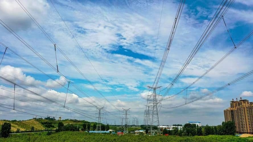
In modern power systems, the three-phase transformer is a fundamental component used to efficiently transmit and distribute large amounts of electricity. Unlike single-phase transformers, three-phase transformers handle power across three conductors simultaneously, making them ideal for industrial and utility-scale applications. Understanding how these transformers work helps clarify their critical role in delivering balanced, reliable power in an interconnected grid.
What Is a Three-Phase Transformer?

Three-phase electrical systems are the backbone of industrial and utility-scale power networks, offering high efficiency and consistent power delivery. To interface between different voltage levels in these systems, we rely on three-phase transformers—specialized equipment designed to handle three-phase current simultaneously across primary and secondary windings. Without them, power transmission, distribution, and industrial operations at scale would be nearly impossible.
A three-phase transformer is an electrical device that transfers electrical energy between two three-phase AC systems at different voltage levels, using a magnetic core and three sets of windings. It either steps up (increases) or steps down (reduces) voltage in three-phase networks while maintaining balanced power across all three phases. Three-phase transformers are essential for power generation, transmission, and large-scale industrial applications.
In this article, we break down how a three-phase transformer works, its configurations, construction, and why it's indispensable in modern electrical infrastructure.
A three-phase transformer consists of three sets of windings that operate simultaneously on a shared magnetic core to transfer power across three-phase systems.True
Each set of windings corresponds to one phase, and the transformer synchronously handles all three phases of power.
Three-phase transformers can only step up voltage, not step down.False
Depending on winding configuration, a three-phase transformer can step up or step down voltage between systems.
1. Basic Function and Working Principle
A three-phase transformer operates on the principle of electromagnetic induction. It includes:
- Three primary windings connected to the high-voltage side
- Three secondary windings connected to the low-voltage side
- A shared laminated magnetic core for mutual induction
Core Functions:
- Transfer power from one voltage level to another
- Maintain phase separation and balance
- Isolate circuits electrically while transferring power magnetically
| Component | Function |
|---|---|
| Primary winding | Receives input voltage |
| Magnetic core | Couples magnetic flux to all phases |
| Secondary winding | Delivers transformed voltage to the load |
2. Construction Types
There are two common structural forms:
| Type | Description | Typical Use Case |
|---|---|---|
| Core-type | Each limb has both primary and secondary windings | Common in medium-to-large transformers |
| Shell-type | Windings are surrounded by magnetic core on all sides | Used in low-voltage, high-current applications |
Assembly:
- Windings can be concentrically arranged on each limb
- Core is typically three-limbed laminated steel
3. Connection Configurations
Three-phase transformers can be wired internally in various configurations to suit voltage and load requirements:
| Configuration | Symbol | Application |
|---|---|---|
| Delta–Delta | Δ–Δ | Industrial motors, balanced loads |
| Star–Star | Y–Y | High-voltage transmission |
| Delta–Star | Δ–Y | Common in distribution (e.g., 11/0.4 kV) |
| Star–Delta | Y–Δ | Step-up transformers at generation |
Dyn11 is a common configuration where the primary is Delta and secondary is Star with 30° phase shift.
4. Advantages of Three-Phase Transformers
| Advantage | Benefit |
|---|---|
| Efficient power delivery | Reduces conductor material by \~25% vs. single-phase |
| Balanced load distribution | Minimizes phase unbalance in power flow |
| Compact and cost-effective | Smaller footprint and lower cost than 3 single-phase units |
| Simpler installation and control | Single tank, core, and protection system |
5. Applications of Three-Phase Transformers
| Sector | Example Use |
|---|---|
| Utility power grid | Transmission (e.g., 132/33 kV substations) |
| Industrial plants | Powering motors, machines, furnaces |
| Renewable energy | Grid-tie from solar/wind farms (e.g., 33/11 kV) |
| Large commercial | Shopping malls, office towers, hospitals |
| Data centers | Feeding high-density server loads |
6. Comparison: Three-Phase vs. Single-Phase Transformers
| Feature | Three-Phase Transformer | Single-Phase Transformer |
|---|---|---|
| Phases handled | 3 simultaneously | 1 |
| Efficiency | Higher | Lower |
| Cost per kVA | Lower | Higher |
| Footprint | Smaller (for same rating) | Larger |
| Application scale | Industrial, utility-scale | Residential, light load |
Summary Table: Key Specifications of a Typical 3-Phase Transformer
| Parameter | Typical Value |
|---|---|
| Power Rating | 100 kVA – 500 MVA |
| Voltage Class | 11/0.4 kV, 33/11 kV, 220/132 kV |
| Cooling Type | ONAN, ONAF, OFAF |
| Vector Group | Dyn11, YNd1, YNyn0, etc. |
| Frequency | 50 or 60 Hz |
| Insulation Class | Class A/B/F (depending on temp) |
How Does a Three-Phase Transformer Operate?
Three-phase transformers are the heart of industrial and utility-scale electrical power systems, and understanding their operation is essential for professionals in power engineering. They work by simultaneously transferring energy between three alternating currents (phases) through electromagnetic induction, enabling voltage conversion and system isolation across a shared magnetic core. When designed and operated correctly, they provide balanced, efficient, and stable power delivery over long distances and high loads.
A three-phase transformer operates by using electromagnetic induction across three separate but magnetically linked sets of windings (one for each phase) arranged on a shared magnetic core. Each phase of AC current in the primary winding generates alternating magnetic flux, which induces voltage in the corresponding secondary winding. These phases are spaced 120° apart, allowing simultaneous and balanced power transfer in three-phase systems.
This article provides a professional, in-depth explanation of how three-phase transformers operate—from core theory and phase behavior to flux flow and voltage transformation—equipping engineers and technicians with a clear, accurate understanding of this critical equipment.
Each winding in a three-phase transformer corresponds to one phase and functions through electromagnetic induction with its magnetic core limb.True
Three windings, one per phase, are magnetically coupled via a shared core to transfer energy efficiently across voltage levels.
Three-phase transformers require three completely separate magnetic cores for each phase.False
A single magnetic core with three limbs is typically used, where each limb supports one phase and the fluxes interact to optimize magnetic path usage.
1. Fundamentals of Operation: Electromagnetic Induction in Three Phases
Working Principle:
Three-phase transformers use Faraday’s Law of Electromagnetic Induction:
- AC current in the primary windings generates alternating magnetic flux
- This flux is channeled through the shared core
- Induces a voltage in the secondary windings, which are magnetically linked to the same core
Each phase:
- Has its own pair of windings (primary and secondary)
- Is spaced 120° electrically from the others
- Shares the magnetic path with other phases
| Component | Function |
|---|---|
| Primary winding | Receives input voltage from the source |
| Core limb | Conducts magnetic flux |
| Secondary winding | Induces output voltage to the load |
2. Magnetic Flux Flow in the Core
Core Design:
A typical three-phase transformer has:
- Three limbs—one for each phase (A, B, C)
- Magnetic flux from each phase adds vectorially
Balanced Operation:
- At any instant, the vector sum of the three magnetic fluxes = 0
This allows for:
- Efficient magnetic coupling
- Smaller core size than three individual single-phase transformers
| Time Snapshot | Phase A Flux | Phase B Flux | Phase C Flux | Total Core Flux |
|---|---|---|---|---|
| t₀ | +Φ | -0.5Φ | -0.5Φ | 0 |
The balanced cancellation of flux ensures smooth and synchronized operation.
3. Voltage Transformation Mechanism
Voltage Conversion:
- Each winding pair operates like a single-phase transformer
- Voltage is determined by turns ratio (N₁/N₂)
Formula:
$V_2 = \left(\frac{N_2}{N_1}\right) \times V_1$
Where:
- $V_1$ = Primary voltage
- $V_2$ = Secondary voltage
- $N_1, N_2$ = Primary and secondary turns
Example:
- 11 kV/0.415 kV transformer
- Each phase steps voltage down from 11,000 V to 415 V phase-to-neutral
- Line-to-line output (L-L) = 415 V × √3 ≈ 720 V (depending on configuration)
4. Transformer Connection and Phase Relationships
| Connection Type | Phase Relationship | Usage Example |
|---|---|---|
| Star–Star (Y–Y) | Line voltage = √3 × phase voltage | Long-distance transmission, HV systems |
| Delta–Delta (Δ–Δ) | No neutral, phase = line voltage | Industrial loads, motor banks |
| Delta–Star (Δ–Y) | Neutral on secondary | Distribution transformers (e.g., 11/0.4 kV) |
| Star–Delta (Y–Δ) | Step-up transformers at generation | Generator step-up (GSU) units |
Proper vector group selection (e.g., Dyn11) ensures correct phase displacement and synchronization across systems.
5. Current and Power Behavior
In a balanced system:
- Current in each phase is equal in magnitude and 120° apart in time
- Total power (P):
$$
P = \sqrt{3} \times V_L \times I_L \times \cos(\phi)
$$
Where:
- $V_L$: Line voltage
- $I_L$: Line current
- $\cos(\phi)$: Power factor
This ensures continuous power flow with minimal pulsation, ideal for motors and industrial equipment.
6. Cooling and Efficiency Considerations
During operation:
- Losses generate heat: core losses (hysteresis, eddy currents) and copper losses (I²R)
Heat is removed by:
- ONAN (Oil Natural Air Natural)
- ONAF (Oil Natural Air Forced)
- ODAF/OFWF for large power units
| Efficiency Factor | Impact on Operation |
|---|---|
| Core loss | Constant, due to voltage application |
| Copper loss | Variable, depends on load current |
| Temperature rise | Must be controlled via cooling system |
7. Three-Phase Transformer in Action: Real Case
Application Example:
- Transformer: 33/11 kV, 10 MVA, Dyn11
- Primary: 3-phase 33 kV Delta
- Secondary: 3-phase 11 kV Star with neutral
Operation Flow:
- Grid supplies 33 kV to Delta side
- Magnetic flux induces voltage on secondary
- 11 kV appears across each Star winding
- Power flows to downstream feeders for distribution
Summary Table: Key Operation Characteristics
| Feature | Description |
|---|---|
| Number of phases | 3 |
| Magnetic limbs | 3 (one per phase) |
| Winding sets | 3 primary + 3 secondary |
| Power flow | Simultaneous across all three phases |
| Voltage regulation | By OLTC (in larger units) |
| Efficiency | >98% in well-designed systems |
What Are the Common Types of Three-Phase Transformers?
In three-phase power systems, transformers are crucial for stepping voltage levels up or down to suit generation, transmission, and consumption needs. However, not all three-phase transformers are created equal. Their design, construction, cooling method, and core configuration vary significantly depending on the voltage class, load demand, location, and safety requirements. Selecting the correct type is key to ensuring performance, reliability, and efficiency under operational conditions.
The most common types of three-phase transformers include core-type and shell-type based on construction; oil-immersed and dry-type based on cooling and insulation; and autotransformers for efficient voltage conversion within similar voltage levels. Each type is tailored to specific voltage ranges, installation environments, and operational requirements.
This article presents a clear overview of these transformer types, outlining how they differ, where they’re used, and why selecting the right one matters.
There are multiple types of three-phase transformers, each designed for specific construction, cooling, and application requirements.True
Transformer types vary based on core structure, insulation method, cooling system, and use case, allowing optimal design for each electrical environment.
All three-phase transformers are oil-immersed by default and cannot be built as dry-type units.False
Dry-type transformers are widely used in indoor, fire-sensitive, or commercial environments, offering safe, air-cooled operation without oil.
1. Core-Type vs. Shell-Type Transformers
These classifications are based on the core and winding configuration.
| Type | Description | Applications |
|---|---|---|
| Core-Type | Windings surround each limb of the magnetic core | Widely used in high-voltage transmission |
| Shell-Type | Core surrounds windings on both sides | Low-voltage, high-current environments |
Comparison:
| Parameter | Core-Type | Shell-Type |
|---|---|---|
| Magnetic flux path | Single-loop | Dual-loop |
| Mechanical strength | Lower | Higher |
| Heat dissipation | Easier | More confined |
| Construction cost | Lower | Higher |
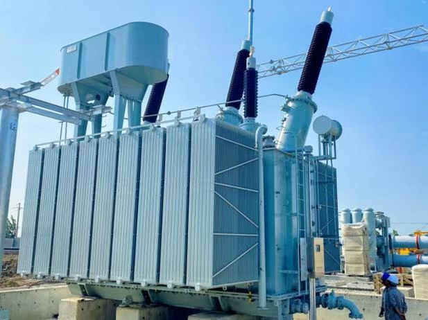
2. Oil-Immersed Transformers (Liquid-Filled)
The most common type used in distribution and transmission systems.
Features:
- Windings and core submerged in mineral or ester oil
- Oil acts as insulator and coolant
Cooling can be:
- ONAN (Oil Natural, Air Natural)
- ONAF (Oil Natural, Air Forced)
- ODAF (Oil Directed, Air Forced)
| Use Case | Application Example |
|---|---|
| Outdoor substations | 132/33 kV or 33/11 kV transformers |
| Renewable energy systems | Grid-tie transformers |
| High-load industrial zones | Step-down transformers |
Pros:
- High efficiency
- Suitable for high power ratings (>1 MVA)
- Long service life with proper maintenance
Cons:
- Fire risk (mineral oil)
- Requires oil containment
- Needs regular oil testing and conditioning
3. Dry-Type Transformers (Air-Cooled)
Widely used in indoor and fire-sensitive areas where oil is a risk.
Types:
- VPI (Vacuum Pressure Impregnated) resin-coated windings
- Cast Resin with fully encapsulated coils
| Ideal Environments | Features |
|---|---|
| Hospitals, malls, data centers | No oil, fire-safe, low maintenance |
| Underground installations | Compact and environment-friendly |
Pros:
- No fire hazard
- Lower environmental impact
- Simple maintenance (no oil management)
Cons:
- Lower power ratings (usually <5 MVA)
- Poorer overload tolerance
- Higher initial cost
4. Three-Phase Autotransformers
Use shared windings for primary and secondary sides—ideal for small voltage differences.
| Feature | Description |
|---|---|
| Winding economy | Uses fewer materials (copper/iron) |
| Size | More compact than dual-winding types |
| Cost | Lower for similar power rating |
Use Cases:
- Interconnection between 132/110 kV or 66/33 kV
- Industrial voltage regulation
- Generation step-up transformers
Caution:
- No electrical isolation between input and output
- Not suitable for systems requiring galvanic separation
5. Three-Phase Pad-Mounted Transformers
Compact units designed for urban or underground distribution.
Features:
- Completely enclosed steel tank
- Front-accessible HV and LV compartments
- Oil-filled with tamper-proof design
| Use Case | Example |
|---|---|
| Urban distribution networks | Residential transformers (11/0.4 kV) |
| Commercial/industrial zones | Building service entry transformers |
6. Cast Resin Three-Phase Transformers
Specialized form of dry-type transformers with:
- Encapsulated coils in epoxy resin
- High mechanical and moisture resistance
Use Case:
- Harsh environments (tunnels, mines, marine, offshore rigs)
- Short-circuit-prone environments
| Feature | Benefit |
|---|---|
| No oil | Fire-safe, pollution-resistant |
| Fully sealed | Operable in 95%+ humidity |
| Long life span | Resistant to vibrations/impacts |
Summary Table: Common Types of Three-Phase Transformers
| Type | Core Type | Cooling Type | Power Rating Range | Typical Applications |
|---|---|---|---|---|
| Core-Type | Core | Oil or Dry | 100 kVA–500 MVA | Substations, utilities |
| Shell-Type | Shell | Oil or Dry | Up to 5 MVA | Short, high-current loads |
| Oil-Immersed | Core/Shell | ONAN, ONAF, OFAF | 1 MVA–1000+ MVA | Grid transmission, industry |
| Dry-Type | Core/Shell | AN or AF | ≤5 MVA | Indoor buildings, commercial zones |
| Autotransformer | Core | Oil-cooled | 10 MVA–1000+ MVA | HV interconnection with low ΔV |
| Pad-Mounted | Core | Oil-filled | 50–2500 kVA | Urban low-voltage distribution |
| Cast Resin | Shell | Air-cooled | 100 kVA–3 MVA | Tunnels, marine, explosive zones |
What Are the Typical Connection Configurations?
The connection configuration of a three-phase transformer is a critical design parameter that defines how its primary and secondary windings are electrically connected. These configurations determine phase relationships, neutral availability, voltage transformation, and suitability for parallel operation. Selecting the proper configuration—such as Delta–Star (Δ–Y), Star–Delta (Y–Δ), Star–Star (Y–Y), or Delta–Delta (Δ–Δ)—is vital for transformer compatibility with the system’s operational requirements.
Typical connection configurations of three-phase transformers include Delta–Delta (Δ–Δ), Star–Star (Y–Y), Delta–Star (Δ–Y), and Star–Delta (Y–Δ). These arrangements define the winding topology on both the primary and secondary sides, impacting voltage ratios, phase displacement, grounding, and system compatibility. Choosing the right configuration ensures reliable operation, efficient voltage transformation, and proper fault current behavior.
This article provides an in-depth, technically grounded guide to each configuration, their use cases, advantages, and associated vector groups.
Connection configurations such as Delta–Star or Star–Delta define how a transformer's windings are connected and influence system grounding and phase shift.True
Transformer connection types determine whether a neutral is available, the phase angle between primary and secondary voltages, and the suitability for certain loads or grid integration.
All transformers must use the same Delta–Star configuration regardless of the application.False
Different applications require different configurations—Delta–Star is common in distribution, while Delta–Delta or Star–Star are often used in transmission or balanced industrial systems.
1. Delta–Delta (Δ–Δ) Connection
Configuration:
- Primary and secondary windings are each connected in a closed triangle.
Features:
- No neutral available
- No phase shift between primary and secondary
- Allows ungrounded or floating systems
| Advantage | Description |
|---|---|
| Operates under unbalanced load | Each phase is independent |
| Redundant operation | Can work as open-Delta (V-V) if one winding fails |
| No zero-sequence current path | Suitable for balanced, symmetrical systems |
Use Case:
- Industrial loads with heavy motor operations
- Short-distance transmission in medium voltage
| Vector Group | Common Example |
|---|---|
| Dd0 | No phase shift |
2. Star–Star (Y–Y) Connection
Configuration:
- Both windings connected in “Y” with a common neutral point
Features:
- Phase voltage = line voltage / √3
- Needs phase-shifting device to avoid harmonics under unbalanced load
- Neutral enables grounding and single-phase loads
| Advantage | Description |
|---|---|
| Neutral point availability | Useful for grounding and single-phase loads |
| Simpler winding construction | Especially in dry-type or indoor units |
| Efficient for high voltage | Reduces insulation requirement (phase voltage is lower) |
Disadvantages:
- Harmonic distortion if not properly loaded
- Requires tertiary winding in HV applications for stability
Use Case:
- Long-distance high-voltage transmission
- Grid interconnections
| Vector Group | Common Example |
|---|---|
| Yy0 | No phase shift |
3. Delta–Star (Δ–Y) Connection
Configuration:
- Primary winding in Delta, secondary in Star
- Most widely used for distribution transformers
Features:
- Provides neutral on secondary
- Creates 30° phase shift (lagging or leading depending on vector group)
- Suppresses third harmonics
| Advantage | Description |
|---|---|
| Neutral for mixed load | Supports 3-phase and single-phase loads |
| Ideal for grounding secondary | Stabilizes fault current paths |
| Harmonic isolation | Delta traps third harmonics |
Use Case:
- Step-down transformers (e.g., 11/0.4 kV)
- Commercial and residential distribution
| Vector Group | Common Example |
|---|---|
| Dyn11 | 30° lag (common) |
4. Star–Delta (Y–Δ) Connection
Configuration:
- Primary in Star, secondary in Delta
- Often used in generation step-up transformers
Features:
- Star side allows grounding at generation site
- Delta side balances load with no neutral
- 30° phase shift (leading)
| Advantage | Description |
|---|---|
| Reduces phase voltage on primary | Simplifies insulation on Star side |
| Delta suppresses harmonics | Enhances waveform quality |
| Suited for generator connections | Reliable GSU transformer choice |
Use Case:
- Step-up transformer at power stations
- Grid entry points
| Vector Group | Common Example |
|---|---|
| Yd1 | 30° lead |
5. Zigzag Connection (Z–Y or Y–Z)
Configuration:
- Modified Star winding with split coils per phase
- Neutral formation with better harmonic suppression
Features:
- Common in grounding transformers
- Enables zero-sequence current path without Delta
- Useful in transformer grounding applications
| Advantage | Description |
|---|---|
| Harmonic filtering | Reduces triplen harmonics |
| Stable neutral point | For systems with unbalanced loads |
| Compact neutral grounding method | Avoids need for Delta winding |
Use Case:
- Grounding transformers
- Special-purpose installations (e.g., data centers)
Summary Table: Typical Three-Phase Transformer Connections
| Configuration | Primary | Secondary | Neutral | Phase Shift | Application Example |
|---|---|---|---|---|---|
| Δ–Δ | Delta | Delta | No | 0° | Motors, balanced loads, industry |
| Y–Y | Star | Star | Yes | 0° | HV transmission lines |
| Δ–Y | Delta | Star | Yes | 30° Lag | Distribution (11/0.4 kV) |
| Y–Δ | Star | Delta | No | 30° Lead | Generation step-up (GSU) |
| Zigzag (Z–Y) | Z | Star | Yes | Variable | Neutral grounding, harmonics |
What Are the Main Advantages of Three-Phase Transformers?
Three-phase transformers are essential to the world’s power systems, enabling efficient voltage transformation in generation, transmission, and distribution networks. Unlike their single-phase counterparts, they are specifically designed to handle three-phase current simultaneously—saving space, improving power quality, and reducing cost. Their design and operation make them a preferred solution for industrial and utility-scale applications, where balanced and continuous power flow is critical.
The main advantages of three-phase transformers include higher efficiency, compact construction, balanced power delivery, reduced copper usage, lower installation cost, and easier maintenance compared to using three single-phase transformers. Their ability to manage high power loads and support diverse system configurations makes them ideal for modern electrical infrastructure.
This article explains why three-phase transformers are superior in large-scale electrical systems and highlights the operational, economic, and technical benefits they offer.
Three-phase transformers are more efficient and compact than using three separate single-phase transformers.True
Three-phase transformers share a common magnetic core and tank, reducing material use and footprint while increasing efficiency.
Three-phase transformers cannot be used for balanced industrial loads and are only suited for residential supply.False
They are ideal for industrial applications due to their capacity to handle large, balanced loads and provide stable voltage.
1. Higher Efficiency and Lower Losses
Three-phase transformers are more efficient than equivalent single-phase systems:
- Shared magnetic core = reduced core loss
- Lower copper losses due to optimized conductor usage
- Smaller surface area per unit = less heat generation
| Type | Typical Efficiency (Full Load) |
|---|---|
| Single-phase transformer (100 kVA) | \~96.5% |
| Three-phase transformer (300 kVA) | \~98.5–99.1% |
The efficiency advantage increases as power rating grows, making them ideal for grid and industrial settings.
2. Compact Design and Space Savings
Three-phase transformers are physically smaller and lighter than a bank of three single-phase units:
- Single tank and core design reduces total volume
- Shared enclosures = less installation space
- Easier to transport, mount, and service
| Comparison Metric | Three-Phase Transformer | 3 Single-Phase Units |
|---|---|---|
| Total weight | 100% | 120–130% |
| Installation footprint | 1.0× | 1.5×–2.0× |
| Maintenance access | One enclosure | Three units |
For high-density installations like substations, space and weight savings are critical.
3. Balanced Load Handling
In a three-phase transformer:
- Loads are distributed evenly across three phases
- Reduces chances of voltage imbalance
- Maintains power factor and waveform stability
| Benefit | Result |
|---|---|
| Continuous power flow | No pulsations, ideal for motors |
| Symmetrical phase voltages | Minimizes system harmonics |
| Higher power transfer | √3 × V × I × PF = Total Power |
Especially beneficial in motors, compressors, and power-intensive systems.
4. Cost-Effective and Economical
Compared to three single-phase transformers:
- Requires less material (copper and iron)
- Lower overall manufacturing cost
- Simplified protection and relay setup
| Cost Factor | Three-Phase Transformer | Three Single-Phase Units |
|---|---|---|
| Purchase cost (approx.) | 100% | 130–150% |
| Installation cost | Lower | Higher |
| Maintenance and spares | One unit | Three separate systems |
Utilities and industries benefit from lower lifecycle cost and simpler logistics.
5. Simplified Installation and Connection
Three-phase units feature:
- One common core and tank
- One set of bushings, conservator, and relays
- Faster commissioning compared to installing and aligning three separate units
| Task | Three-Phase TX | Single-Phase Bank |
|---|---|---|
| Foundation | One pad | Three plinths |
| HV/LV connection points | Simplified | Multiplied |
| Testing and tagging | Single process | Triple effort |
Minimizes field labor, wiring complexity, and testing time.
6. Support for Multiple Connection Types
Three-phase transformers allow for various connection schemes (e.g., Delta–Star, Star–Delta, etc.), which enables:
- Phase shift control (e.g., 30° shift in Dyn11)
- Grounding flexibility (neutral availability)
- Parallel operation with other transformers
| Connection Type | Benefit |
|---|---|
| Δ–Y | Neutral for distribution, harmonic isolation |
| Y–Δ | Generator step-up, no neutral |
| Δ–Δ | No phase shift, supports unbalanced loads |
| Y–Y | Simpler construction, less insulation |
These options enhance system compatibility and design flexibility.
7. Robust and Scalable for Industrial Use
Three-phase transformers are designed to handle high power loads in:
- Power plants and substations
- Industrial factories
- Renewable energy tie-ins
- Data centers and mining operations
| Application Area | Power Rating Range |
|---|---|
| Distribution substations | 100 kVA – 2.5 MVA |
| Transmission substations | 5 MVA – 500 MVA+ |
| Industrial plants | 250 kVA – 50 MVA |
| Wind/solar farms | 1–20 MVA (grid-tied) |
Summary Table: Advantages of Three-Phase Transformers
| Advantage | Description |
|---|---|
| High efficiency | Less loss, better thermal behavior |
| Space-saving design | Single core/tank instead of three |
| Cost-effective | Lower material, installation, and maintenance cost |
| Balanced power delivery | Better voltage stability and motor performance |
| Easy to install and maintain | Simplified wiring and access |
| Configurable connections | Support for Delta, Star, Zigzag, etc. |
| Industrial-grade capacity | Handles large, continuous loads reliably |
Where Are Three-Phase Transformers Commonly Used?
Three-phase transformers are essential in modern electrical infrastructure. Their ability to handle large, balanced power loads makes them the preferred solution for high-efficiency voltage transformation across every stage of the power system—from generation to end-user distribution. Whether stepping up voltage for long-distance transmission or stepping it down for commercial and industrial consumption, three-phase transformers provide the backbone of consistent and reliable three-phase power.
Three-phase transformers are commonly used in power generation plants, high-voltage transmission substations, medium- and low-voltage distribution networks, industrial manufacturing facilities, commercial complexes, renewable energy systems, and data centers. They serve as critical components for stepping up or stepping down voltage across three-phase AC networks.
This article explains the most frequent real-world applications of three-phase transformers and highlights why their use is vital for ensuring uninterrupted and efficient power delivery.
Three-phase transformers are widely used across generation, transmission, and distribution networks to step voltages up or down efficiently.True
They are critical at every level of the power system, from power plants and substations to factories and commercial buildings.
Three-phase transformers are only suitable for small residential loads and cannot support industrial-scale power requirements.False
Three-phase transformers are designed specifically for high-capacity loads, making them ideal for heavy-duty industrial and utility applications.
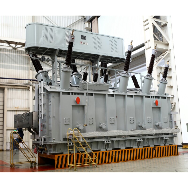
1. Power Generation Plants
Where Used:
- Generator Step-Up (GSU) Transformers
Function:
- Convert generator output voltage (11–22 kV) to high transmission voltage (132–765 kV)
Benefits:
- Enable long-distance power transport
- Minimize I²R losses across transmission lines
- Handle very high MVA ratings (up to 1200 MVA)
| Example Location | Typical Rating |
|---|---|
| Thermal power station | 300 MVA, 22/400 kV |
| Hydro station | 150 MVA, 11/132 kV |
| Nuclear facility | 500 MVA, 24/400 kV |
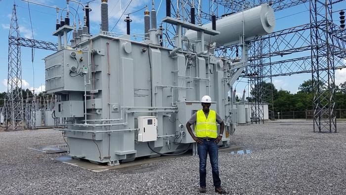
2. High-Voltage Transmission Substations
Where Used:
- Interconnection substations and voltage step-down units
Function:
- Step down transmission voltages (400, 220, 132 kV) to medium-voltage levels (33 or 11 kV) for sub-transmission or industrial use
Benefits:
- Maintain system stability and fault protection
- Interface between transmission and distribution grids
- Use autotransformers or Y–Y / Y–Δ transformers
| Example Installation | Voltage Levels |
|---|---|
| National Grid Substation | 400/132 kV |
| Inter-regional tie point | 220/66 kV |
| Regional utility station | 132/33 kV |
3. Medium-Voltage Distribution Networks
Where Used:
- Distribution substations or pole-mounted transformers
Function:
- Step down 33 or 11 kV to 400/230 V for commercial and residential areas
Benefits:
- Provide three-phase and single-phase supply
- Serve urban and rural distribution
- Most commonly Delta–Star (Δ–Y), e.g., Dyn11
| Typical Use Case | Transformer Rating |
|---|---|
| Urban neighborhood | 250–630 kVA, 11/0.4 kV |
| Rural feeder station | 100 kVA, 33/0.4 kV |
| Small industrial park | 500 kVA, 11/0.4 kV |
4. Industrial and Manufacturing Plants
Where Used:
- Internal power distribution and machinery supply
Function:
- Supply three-phase power to motors, furnaces, conveyor systems, compressors, and process equipment
Benefits:
- Supports balanced, continuous high-power loads
- Enables in-plant voltage control via OLTC
- Can be dry-type or oil-immersed based on environment
| Industry Type | Transformer Role |
|---|---|
| Steel manufacturing | Furnace transformer |
| Chemical plants | Explosion-proof dry-type |
| Mining operations | Mobile oil-filled units |
5. Renewable Energy Systems
Where Used:
- Grid-tied wind farms, solar farms, hydro projects
Function:
- Step up voltage from 400 V–33 kV to grid levels (66–132 kV)
- Inverter output fed into medium-voltage three-phase transformer
Benefits:
- Facilitates grid synchronization
- Mitigates power quality issues via vector group control
- Environmental compliance with FR3 oil or dry-type resin insulation
| Renewable Source | Typical Rating |
|---|---|
| Utility solar farm | 2.5 MVA, 0.4/33 kV |
| Wind farm | 3.0 MVA, 0.69/33 kV |
| Mini-hydro | 5 MVA, 11/132 kV |
6. Commercial Buildings and Infrastructure
Where Used:
- Shopping malls, airports, hospitals, stadiums
Function:
- Step down medium-voltage supply (11/22 kV) to usable levels (400 V)
Benefits:
- Supports HVAC, elevators, lighting, and emergency systems
- Often dry-type for fire safety and ease of indoor installation
- Offers neutral for mixed load support
| Location Type | Transformer Type |
|---|---|
| High-rise buildings | 1000 kVA dry-type, Dyn11 |
| Data centers | Shielded dry-type |
| Transport terminals | 1250 kVA oil-filled |
7. Data Centers and IT Facilities
Where Used:
- Server farms, edge computing hubs, telecom switching centers
Function:
- Maintain clean, stable three-phase supply to UPS, HVAC, and server racks
Benefits:
- Supports redundancy (N+1, 2N architecture)
- Compact, low-loss dry-type units
- Integrated with smart monitoring and harmonic filters
| Facility Example | Power Infrastructure |
|---|---|
| Tier 4 data center | Dual 1500 kVA transformers |
| Edge node shelter | 500 kVA cast resin unit |
Summary Table: Common Uses of Three-Phase Transformers
| Sector/Location | Voltage Levels | Transformer Role |
|---|---|---|
| Power generation | 11–24 kV to 132–400 kV | Generator step-up |
| Transmission substations | 220–400 kV to 132/66 kV | Inter-grid connection |
| Distribution networks | 33/11 kV to 0.4 kV | Public power delivery |
| Industrial facilities | 33/11 kV to 400/690 V | Equipment power supply |
| Renewable energy | 0.4–0.69 kV to 33/66/132 kV | Grid feed integration |
| Commercial buildings | 11/22 kV to 0.4 kV | Power for lighting, HVAC, elevators |
| Data centers | 11/22 kV to 0.4 kV | Clean, uninterrupted IT load supply |
Conclusion
Three-phase transformers are indispensable to modern power infrastructure. Their ability to handle high power levels with efficiency and stability makes them ideal for everything from large factories to nationwide grids. With versatile configurations and proven reliability, understanding their operation and applications is essential for anyone involved in the design, operation, or maintenance of electrical systems.
FAQ
Q1: What is a three-phase transformer?
A1: A three-phase transformer is an electrical device designed to transfer electrical energy between three-phase systems. It steps up or steps down voltage levels across three interconnected windings—one for each phase—making it essential for industrial, commercial, and utility-scale power applications.
Q2: How does a three-phase transformer work?
A2: It operates based on electromagnetic induction. Three primary windings connected in delta or star configuration receive alternating current, creating magnetic flux in the core. This flux induces voltage in three secondary windings, which are also connected in a specific configuration, ensuring balanced three-phase output.
Q3: What are the main configurations of three-phase transformers?
A3: The common configurations are:
Delta–Delta (Δ–Δ)
Delta–Wye (Δ–Y)
Wye–Delta (Y–Δ)
Wye–Wye (Y–Y)
These configurations affect voltage levels, phase angles, and grounding methods, and are selected based on system requirements.
Q4: What are the advantages of using a three-phase transformer?
A4: Advantages include:
Efficient power delivery for large loads
Smaller size and cost compared to three single-phase units
Balanced power with fewer losses
Reliable performance in high-voltage transmission and heavy-duty industrial use
Q5: Where are three-phase transformers commonly used?
A5: They are widely used in:
Electrical substations
Industrial plants
Commercial buildings
Renewable energy systems
Utility-scale power transmission and distribution
References
"Three-Phase Transformers Explained" – https://www.transformertech.com/three-phase-transformer-guide – Transformer Tech
"Working Principle of a Three-Phase Transformer" – https://www.powermag.com/three-phase-transformers-working – Power Magazine
"Configurations and Applications of Three-Phase Transformers" – https://www.electrical4u.com/three-phase-transformer – Electrical4U
"Electromagnetic Induction in Power Transformers" – https://www.sciencedirect.com/three-phase-transformer-principles – ScienceDirect
"Understanding Three-Phase Transformer Operation" – https://www.researchgate.net/three-phase-transformer-operation – ResearchGate
"Smart Grid Integration of Three-Phase Transformers" – https://www.smartgridnews.com/three-phase-transformers-grid – Smart Grid News
"Three-Phase Transformer Uses and Benefits" – https://www.energycentral.com/c/ee/three-phase-transformer-applications – Energy Central
"PowerGrid Guide to Three-Phase Transformer Efficiency" – https://www.powergrid.com/three-phase-transformer-basics – PowerGrid