A faulty or failing transformer can cause significant disruptions in electrical systems. Whether in homes, substations, or industrial plants, understanding the symptoms and consequences of a bad transformer is crucial for timely repair and system reliability.
What Are the Signs of a Bad Transformer?
Transformers are vital components of electrical infrastructure, and when they begin to fail, the consequences can include power outages, fire risks, system failures, or asset loss. A failing transformer rarely goes unnoticed—there are telltale physical, acoustic, thermal, and electrical signs that indicate internal deterioration, insulation failure, or cooling issues. Recognizing these early warning indicators can prevent catastrophic damage, reduce downtime, and extend service life.
Common signs of a bad transformer include unusual humming or buzzing sounds, overheating or hot spots, oil leaks or discoloration, burnt odors, visible charring or corrosion, abnormal voltage output, repeated circuit breaker trips, and insulation test failure. These indicators suggest internal faults such as winding breakdown, core saturation, dielectric failure, or short-circuited turns.
A failing transformer speaks—the key is knowing how to listen.
Signs of a failing transformer include noise, overheating, oil leaks, and unstable voltage output.True
These symptoms often result from insulation degradation, winding faults, or core issues and must be addressed early to avoid transformer failure.
Transformers typically fail without warning and show no external signs.False
Most transformer failures are preceded by physical, thermal, or electrical indicators that can be detected during inspections.
1. Unusual Noise (Humming, Buzzing, Crackling)
| Noise Type | Possible Cause |
|---|---|
| Excessive humming | Core loosening or vibration |
| Crackling or arcing | Partial discharge or insulation breakdown |
| Sudden changes in tone | Magnetic saturation or phase imbalance |
Noise change is often the first audible sign of core lamination or electrical issues.
2. Overheating or Hotspots
| Observation Method | What It Reveals |
|---|---|
| Surface hot to touch | Cooling failure or overload condition |
| IR camera reveals hotspot | Internal winding fault or poor oil circulation |
| Unexplained temperature rise | Load imbalance or poor ventilation |
Overheating accelerates insulation aging and may signal blocked oil flow or coil failure.
3. Oil Leaks or Discoloration
| Leak Location | Associated Fault |
|---|---|
| At gaskets or flanges | Gasket wear, thermal expansion stress |
| Around bushings | Seal deterioration, moisture ingress |
| Discolored or sludged oil | Oxidation, overheating, or contamination |
Leaking or degraded oil leads to loss of dielectric strength and higher fire risk.
4. Burnt Odor or Smoke
| Smell Source | Interpretation |
|---|---|
| Acrid electrical smell | Insulation breakdown inside windings |
| Burnt oil odor | Overheating or internal arc |
| Smoke near terminals | Serious fault—shutdown required |
Odor is often the clearest sensory sign of a transformer fault.
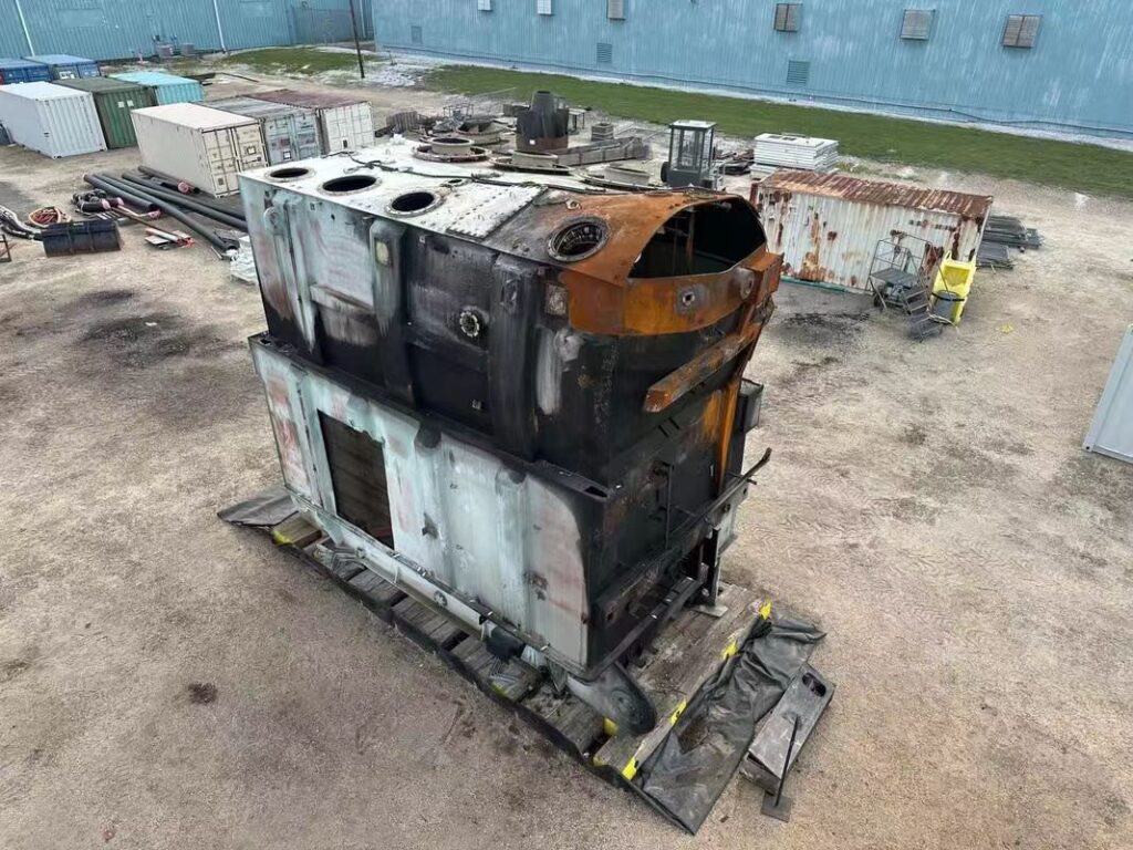
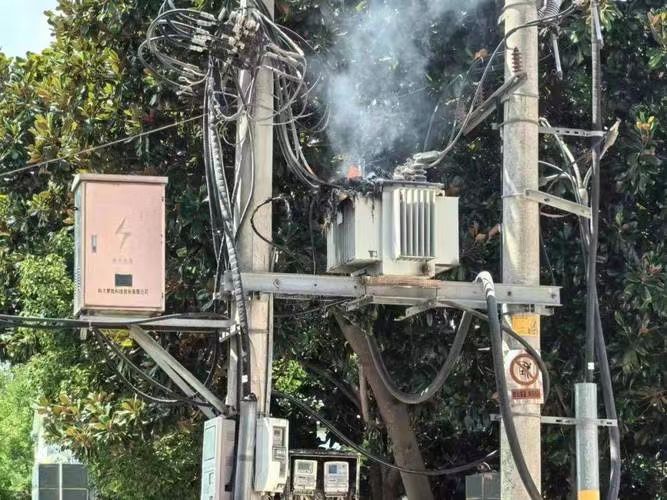
5. Visual Charring, Corrosion, or Bulging
| Visual Symptom | Possible Explanation |
|---|---|
| Blackened paint or burn marks | Arc flash or internal fire |
| Rust or blistered paint | Corrosion and internal moisture damage |
| Bulging tank or radiator | Gas pressure buildup due to insulation failure |
These are signs of critical internal degradation requiring immediate action.
6. Voltage Instability or Load Imbalance
| Electrical Behavior | Meaning |
|---|---|
| Low or fluctuating voltage | Tap changer malfunction or partial short |
| Phase imbalance | Core asymmetry, winding shift, or faulty OLTC |
| Frequent breaker trips | Overcurrent or insulation failure |
Electrical abnormalities can signal core flux issues, partial winding failure, or incorrect tap settings.
7. Dissolved Gas Analysis (DGA) Abnormalities
| Gas Detected | Interpreted Fault |
|---|---|
| Acetylene (C₂H₂) | Arcing |
| Methane/Ethane | Thermal decomposition |
| Carbon monoxide/dioxide | Paper insulation breakdown |
DGA is critical for diagnosing internal faults invisible from the outside.
Summary Table: Signs of Transformer Failure
| Symptom | Indicates |
|---|---|
| Unusual sound | Core looseness, electrical discharge |
| Overheating | Load issue, cooling system failure |
| Oil leak/discoloration | Insulation degradation, contamination |
| Burn smell or smoke | Insulation or winding burnout |
| Visual damage | Arc, corrosion, or thermal bulging |
| Voltage issues | Tap changer failure, shorted turns |
| DGA warning gases | Internal arcing, insulation breakdown |
How Does a Faulty Transformer Affect Voltage Supply?
When a transformer begins to fail, the most noticeable and immediate consequence for downstream systems is voltage instability. Because transformers regulate and adapt voltage across the grid, a fault inside them—whether electrical, mechanical, or thermal—can lead to undervoltage, overvoltage, unbalanced phases, or severe harmonic distortion. This impacts not only homes and industries relying on steady electricity but can also destabilize entire sections of the power grid.
A faulty transformer can cause significant voltage supply issues including voltage drops, overvoltage spikes, phase imbalance, harmonic distortion, and erratic voltage fluctuations. These anomalies result from degraded windings, insulation failure, poor tap changer operation, or core saturation—compromising the transformer's ability to maintain stable and balanced output.
Even a partial fault can disrupt hundreds or thousands of downstream consumers.
A faulty transformer can cause serious voltage supply problems like sag, imbalance, and fluctuation.True
When transformers cannot regulate voltage properly due to internal faults, the entire connected system experiences voltage instability.
Transformer faults only affect the transformer itself and do not impact voltage supply.False
Because transformers are voltage-regulating devices, any internal failure directly affects output voltage stability and grid reliability.
1. Voltage Drop (Undervoltage)
| Cause | Effect on Voltage Supply |
|---|---|
| Partially shorted winding | Reduced voltage transfer efficiency |
| Degraded insulation | Increased internal resistance and energy loss |
| Tap changer malfunction | Incorrect voltage ratio resulting in lower output |
Voltage drops can cause motor stalling, flickering lights, and industrial equipment faults.
2. Overvoltage Spikes
| Trigger | How It Affects Output |
|---|---|
| Open neutral or bushing arc | Surges transferred to the secondary winding |
| Ferroresonance from core failure | Sustained overvoltage conditions |
| Faulty OLTC overshoot | Higher-than-intended voltage delivered |
Overvoltage can damage appliances, stress insulation systems, and trip protective relays.
3. Phase Voltage Imbalance
| Imbalance Source | Grid Consequence |
|---|---|
| Uneven winding damage | One phase delivers less voltage |
| Broken tap mechanism (single phase) | Asymmetrical voltage regulation |
| Neutral displacement | Voltage shift between phases |
Phase imbalance causes equipment overheating, misoperation of motors, and poor power quality.
4. Voltage Fluctuations and Instability
| What Happens | Root Transformer Issue |
|---|---|
| Voltage fluctuates erratically | Loose winding turns, internal arcing, core saturation |
| Inconsistent output | Failing OLTC or temperature-driven winding distortion |
| Flicker and waveform noise | Magnetic flux instability or partial discharges |
These symptoms degrade power quality and affect sensitive electronic devices.
5. Waveform Distortion and Harmonics
| Transformer Fault | Harmonic Impact |
|---|---|
| Core saturation | Generates odd harmonics (e.g., 3rd, 5th, 7th) |
| Loose coil or bad connection | Introduces electrical noise and waveform deformation |
| Improper grounding | Raises neutral-ground voltage, distorts waveform |
Harmonics affect inverter-driven systems, UPSs, and industrial controls, often causing premature failure.
6. Sudden Voltage Collapse (Severe Fault)
| Failure Type | Grid Response |
|---|---|
| Short-circuited winding | Output drops to zero or triggers shutdown |
| Explosive fault (e.g., bushing blowout) | Triggers protective tripping, disconnecting entire segment |
| Fault current through transformer | Causes grid instability or cascading outage |
Major faults may lead to blackouts, transformer fires, or regional service interruptions.
Summary Table: Voltage Effects of Transformer Faults
| Fault Condition | Voltage Supply Impact |
|---|---|
| Partial winding short | Undervoltage, load imbalance |
| Core saturation | Harmonics, waveform distortion |
| OLTC malfunction | Voltage swings, phase mismatch |
| Insulation breakdown | Irregular voltage drops and spikes |
| Tap wear or arcing | Intermittent voltage variation |
| Bushing crack or arc | Overvoltage surges and shutdowns |
Can a Bad Transformer Cause Power Outages or Equipment Damage?
A failing transformer is more than a maintenance issue—it is a direct threat to power reliability and equipment safety. When transformer components degrade, break down, or short-circuit, the consequences ripple through the entire electrical system. This includes service interruptions, burnt appliances, industrial process failure, and even fire hazards. Whether it's a distribution transformer on a city pole or a 500 MVA substation unit, a bad transformer can bring down entire segments of the grid.
Yes, a bad transformer can cause localized or widespread power outages and damage connected equipment. Failures such as insulation breakdown, winding short-circuit, tap changer malfunction, or oil leaks can lead to voltage irregularities, complete transformer shutdown, arcing, or explosions. These events disrupt supply continuity and may overheat or destroy electronic and electrical devices.
A single transformer failure can disrupt thousands of customers and millions of dollars in assets.
A bad transformer can cause power outages and damage downstream electrical equipment.True
Transformer faults disrupt voltage supply and power stability, leading to outages and potentially destructive voltage fluctuations.
Transformer faults only affect the transformer and not the electrical system or user devices.False
A bad transformer alters voltage, balance, and continuity—causing downstream grid damage and equipment malfunction.
1. Types of Power Outages Caused by Transformers
| Transformer Failure Mode | Grid Consequence |
|---|---|
| Internal short circuit | Trip of protective relays, supply cut |
| Bushing explosion or flashover | Immediate outage in substation or feeder |
| Tap changer stuck in wrong tap | Voltage sag or spike causing blackout |
| Oil leak with pressure drop | Trigger Buchholz relay and isolate transformer |
Even localized faults can cascade into feeder or regional blackouts if not contained.
2. Voltage Instability and Equipment Damage
| Voltage Problem | Effect on Equipment |
|---|---|
| Sustained overvoltage | Burnt motors, melted wiring, UPS overload |
| Sagging or undervoltage | HVAC shutdowns, brownouts, inverter misfire |
| Phase imbalance | Three-phase motor overheating, relay errors |
| High-frequency harmonics | Corruption of PLCs, sensors, and medical devices |
Sensitive devices like refrigerators, computers, LED lights, and industrial PLCs are highly vulnerable.
3. Fire and Arc Hazard to Infrastructure
| Transformer Fault Type | Fire/Explosion Risk |
|---|---|
| Internal arc fault | Vaporizes oil, builds pressure → explosion |
| Bushing crack or spark-over | Ignites surface contaminants |
| Tank deformation or bulge | May rupture under internal gas formation |
Transformer explosions have caused substation fires, city-wide outages, and structural damage.
4. Real-World Impacts of Transformer Failure
| Scenario | Outcome |
|---|---|
| Distribution transformer failure | 100–2,000 homes lose power |
| GSU (generator transformer) fault | Whole power plant disconnected from grid |
| Substation power transformer loss | Industrial blackout or partial city shutdown |
| Transformer flashover in storm | Simultaneous outages + public safety hazard |
In many cases, equipment failure and power loss occur within milliseconds of the fault.
5. How Damage Spreads to Equipment
| Cause | Damage Mechanism |
|---|---|
| High voltage transient | Punches through appliance insulation |
| Neutral shift in phase imbalance | Overloads single-phase equipment |
| Sudden re-energizing surges | Inrush current damages cold or idle devices |
| Repeated voltage swings | Cumulative degradation of semiconductors |
Repeated exposure can silently damage devices before complete failure occurs.
Summary Table: Transformer Fault Impact
| Fault Type | Outage Risk | Equipment Risk |
|---|---|---|
| Winding short-circuit | High | Burnout, fire hazard |
| Core insulation failure | Moderate to high | Voltage instability |
| OLTC malfunction | Medium | Over/undervoltage to connected loads |
| Oil leakage and thermal rise | High over time | Silent degradation, overheating |
| Bushing failure | Severe and sudden | Flashover, surge damage to electronics |
What Types of Internal Failures Occur in Bad Transformers?
When a transformer operates continuously under high load, environmental stress, or electrical disturbances, internal components can degrade or fail without visible external signs—until the failure becomes severe. These internal failures can lead to power outages, costly replacements, or catastrophic explosions. Understanding the main types of internal failures is crucial for preventive maintenance and long-term electrical safety.
Internal transformer failures include insulation breakdown, winding deformation, core faults, dielectric oil contamination, bushing failures, tap changer malfunctions, and overheating. These failures compromise the transformer's electrical integrity and may result in operational loss, energy inefficiency, or dangerous system-wide faults.
Each failure type originates from different causes—aging, stress, contamination, or overloading—but they all lead to a common outcome: loss of reliability and safety.
Internal transformer failures are among the leading causes of power outages in industrial and utility systems.True
Failures such as winding shorts or insulation breakdowns directly impact transformer function, often triggering shutdowns or safety trips.
A failing transformer rarely shows immediate external signs. Internal deterioration accumulates over time, making diagnostics and early intervention critical. Let’s explore these failures in detail:
1. Winding Deformation and Short Circuits
Windings are exposed to electromagnetic forces and thermal cycling. Over time, this leads to:
| Cause | Failure Effect |
|---|---|
| Overcurrent or fault events | Turn-to-turn short circuits |
| Mechanical stress | Winding displacement or buckling |
| Insulation wear | Layer-to-layer faults |
Such damage results in overheating, impedance imbalance, and power loss.
2. Insulation Degradation
Transformer insulation (solid and liquid) is the dielectric barrier. Failure here is catastrophic.
| Degradation Agent | Resulting Condition |
|---|---|
| Heat and oxidation | Reduced dielectric strength |
| Moisture contamination | Partial discharge and arc inception |
| Aging cellulose paper | Cracking and loss of integrity |
Insulation breakdown leads to flashovers and high-voltage breakdowns inside the unit.
3. Magnetic Core Damage or Shift
The laminated core must maintain magnetic uniformity.
| Failure Type | Effect on Operation |
|---|---|
| Shorted laminations | Eddy current increase and heat loss |
| Core displacement | Vibration and magneto-mechanical noise |
| Loose clamping | Mechanical instability |
Core faults cause increased no-load losses and core overheating.
4. Tap Changer Wear or Arcing (OLTC/DETC)
Tap changers regulate output voltage and are moving parts prone to wear.
| Problem | Operational Impact |
|---|---|
| Contact erosion | Arcing and carbonization |
| Mechanical misalignment | Voltage drift or no connection |
| Arcing chamber failure | Oil contamination and fire hazard |
Tap changer faults lead to unregulated output or internal arc ignition.
5. Dielectric Oil Contamination
The insulating oil performs both cooling and dielectric functions.
| Contaminant | Impact on System |
|---|---|
| Water/moisture | Reduces breakdown voltage |
| Acids from oxidation | Corrode windings and sludge formation |
| Gases from arcing (e.g., H₂, C₂H₂) | Indicator of severe internal faults |
Dirty oil accelerates thermal and electrical aging.
6. Bushing Failure
Bushings are high-voltage terminals and insulation interfaces.
| Failure Mode | Consequence |
|---|---|
| Dielectric puncture | Internal short circuit |
| Tracking and corona | Surface erosion, eventual flashover |
| Capacitor failure (in HV bushings) | Explosion or rupture |
Often misdiagnosed, bushing failures are a major explosion risk.
7. Thermal Overload and Hot Spots
Overloaded transformers develop thermal gradients internally.
| Overload Type | Effect |
|---|---|
| Steady thermal load | Insulation softening and degradation |
| Transient overloads | Sudden winding expansion or oil stress |
| Cooling failure | Accelerated aging and hotspots |
Heat-related failures silently degrade a transformer's core integrity.
Transformer Failure Matrix
| Failure Type | Root Cause | Impact Severity |
|---|---|---|
| Winding deformation | Short circuit force, vibration | ⚠️ Severe |
| Insulation breakdown | Aging, heat, contamination | 🔥 Catastrophic |
| Core faults | Mechanical stress, vibration | ⚠️ Medium to severe |
| Tap changer malfunction | Wear, poor maintenance | ⚠️ Moderate |
| Oil degradation | Thermal stress, oxidation | ⚠️ High |
| Bushing failure | Moisture, tracking, discharge | 🔥 Explosion risk |
| Overheating | Poor ventilation or overloading | ⚠️ Gradual to severe |
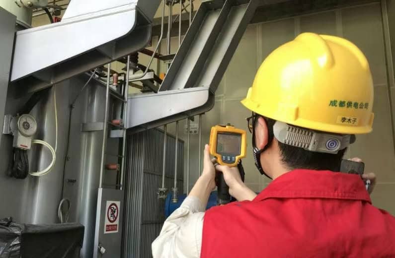
Diagnostic Tools to Identify Internal Failures
| Tool | Detectable Issues |
|---|---|
| Dissolved Gas Analysis | Arcing, overheating, insulation breakdown |
| Sweep Frequency Response | Winding displacement or deformation |
| Infrared Thermography | Hot spots, cooling failure |
| Power Factor Testing | Insulation health |
| Bushing Tan Delta | Bushing condition and aging |
What Are the Safety Hazards of a Malfunctioning Transformer?
In power systems, transformers are crucial yet vulnerable assets. When they malfunction, the consequences extend far beyond equipment downtime—they threaten lives, disrupt grids, and incur massive financial and environmental losses. A single undetected fault can trigger fires, explosions, and toxic leaks. For utilities, manufacturers, or facility managers, failing to recognize and mitigate these hazards can lead to irreversible damage.
A malfunctioning transformer poses serious safety hazards including fire and explosion risk, toxic oil leakage, electrocution, environmental contamination, and equipment damage. These dangers can affect personnel safety, interrupt electricity supply, and cause widespread infrastructure failure if not promptly addressed.
Understanding these hazards isn’t just an engineering concern—it’s a critical safety priority for anyone responsible for maintaining or operating high-voltage equipment.
Malfunctioning transformers frequently cause industrial fires and electrical accidents.True
Insulation breakdown, oil ignition, and internal arcing can result in fires, explosions, or electrocution if left unchecked.
Even minor anomalies in transformer operation can escalate rapidly into dangerous scenarios. Let’s examine the major safety hazards associated with transformer malfunctions:
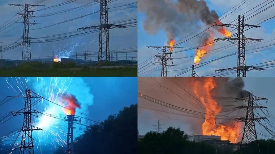
1. Fire and Explosion Hazard
Malfunctioning transformers are one of the leading causes of electrical fires in substations and industrial facilities.
| Root Cause | Hazard Result |
|---|---|
| Internal arcing or short circuit | Oil ignition and fire |
| Overheating of windings | Thermal runaway and combustion |
| Tap changer failure | Contact sparking and arc flashes |
| Bushing breakdown | External flashover or explosion |
Oil-immersed transformers are especially vulnerable, as the dielectric oil is combustible under arc or heat conditions. The release of explosive gases like hydrogen and acetylene during faults can result in violent pressure surges, leading to explosions.
2. Electrocution and Arc Flash Risk
High-voltage transformers, even in a standby state, carry latent electric energy. A failure can result in:
- Live casing or exposed terminals
- Arc flash with temperatures > 19,000°C (34,200°F)
- Electromagnetic fields causing flashovers at a distance
| Scenario | Personnel Risk |
|---|---|
| Faulty ground connection | Step and touch potential injuries |
| Arcing at terminals | Severe burns or death |
| Unexpected energization | Lethal voltage exposure |
Personal Protective Equipment (PPE) and lockout-tagout (LOTO) protocols are essential when working around or near suspect equipment.
3. Toxic Oil Leaks and Chemical Exposure
Many transformers use mineral oil or silicone-based fluids as coolants. These fluids, when degraded or leaked, pose both toxic and environmental risks.
| Leak Component | Hazard |
|---|---|
| PCB (polychlorinated biphenyls)* | Carcinogenic, environmental pollutant |
| Heated oil mist | Inhalation risk and skin irritation |
| Sludge or contaminated residue | Biohazard to soil and water systems |
*While PCBs have been banned in many countries, older transformers may still contain them.
4. Environmental Contamination
Oil and insulating fluid leaks not only present toxic hazards but also contribute to soil and water contamination. When leaks occur:
- Oil seeps into the ground, affecting aquifers and vegetation
- Rain spreads contaminants to stormwater systems
- Fire suppression runoff (foam/water mix) adds to chemical spread
Many utility operators must adhere to EPA, REACH, or local environmental compliance laws, and violations can result in hefty fines.
5. System-Wide Electrical Damage
Transformer failures often cascade into other parts of the power system.
| Failure Consequence | Wider System Impact |
|---|---|
| Sudden loss of voltage regulation | Equipment burnout or grid instability |
| Fault current propagation | Relay miscoordination and blackouts |
| Overvoltage backfeed | Damage to connected loads or circuits |
This becomes particularly dangerous in data centers, hospitals, and industrial control systems, where even a momentary failure is unacceptable.
Safety Hazard Matrix for Malfunctioning Transformers
| Hazard | Primary Cause | Risk Severity | Affected Area |
|---|---|---|---|
| Fire/Explosion | Oil ignition, arcing | 🔥 Extreme | Facility-wide |
| Electrocution | Terminal exposure, arc flash | ⚠️ High | Maintenance personnel |
| Toxic fluid exposure | Oil leakage, ruptured casing | ⚠️ Moderate | Environment & staff |
| System disruption | Fault propagation | ⚠️ High | Network-wide |
| Environmental damage | Contaminated runoff | ⚠️ Severe | Soil, water, and wildlife |
Visual Signs of Dangerous Transformer Failure
| Visual/Auditory Sign | Likely Hazard |
|---|---|
| Smoke or burning smell | Internal insulation fire |
| Oil puddles around base | Toxic leakage |
| Loud buzzing, popping, or arcing | Impending explosion or arcing event |
| Discolored or bloated casing | Thermal stress or internal pressure |
| Ground fault trip (relay event) | Electrical discharge or short circuit |
Mitigation Measures
To protect people, property, and the environment from transformer-related hazards, use a combination of proactive maintenance, engineering safeguards, and operational vigilance:
- Install fire barriers and blast walls around large oil-filled units.
- Use non-flammable fluids (e.g., ester-based coolants) in sensitive areas.
-
Deploy monitoring systems like:
- Dissolved Gas Analysis (DGA)
- Bushing monitoring
- Infrared thermography
- Regularly test grounding, bushings, and oil samples.
- Create emergency response plans, including fire drills and spill containment.
How Should a Bad Transformer Be Diagnosed and Replaced?
Transformer failure is a serious issue that can cause system outages, equipment damage, and safety hazards. If not properly diagnosed and addressed, a failing transformer can compromise power reliability and even lead to catastrophic incidents like fire or explosion. Facility managers, utility engineers, and industrial operators must act quickly and methodically when symptoms appear. The key to avoiding escalation is a structured diagnosis process followed by precise and safe replacement procedures.
To diagnose and replace a bad transformer, professionals must first conduct a series of visual inspections and electrical tests, such as insulation resistance, winding resistance, turns ratio, and dissolved gas analysis. If failure is confirmed, de-energization, safe removal, oil drainage (if applicable), site prep, and installation of the new transformer are performed following strict safety and regulatory guidelines.
Getting the diagnosis and replacement process right is critical to restoring system stability, ensuring operational continuity, and minimizing costs.
Transformers must be properly tested before removal to confirm failure and prevent unnecessary downtime.True
Reliable diagnosis through industry-standard tests such as insulation resistance and DGA helps ensure that only truly failed transformers are replaced.
Transformer diagnostics and replacement involve both technical precision and field safety protocols. Here is a detailed step-by-step process:
Step 1: Initial Visual Inspection and Symptom Reporting
A bad transformer often shows early signs:
- Unusual noise (humming, crackling)
- Oil leaks or stains
- Discolored or bloated casing
- Tripped relays or protective devices
- Overheating or burning odor
Operators should log operational anomalies, including trip events, load behavior, and external damage.
| Visual Indicator | Possible Issue |
|---|---|
| Leaking oil around tank | Gasket failure or overpressure |
| Discolored bushings | Corona discharge or thermal breakdown |
| Carbon deposits | Arcing or internal breakdown |
| Burnt smell or smoke | Winding insulation failure |
Step 2: Electrical Testing and Data Evaluation
This step confirms whether internal damage has occurred. Several tests are performed:
| Test | Purpose | Typical Tool |
|---|---|---|
| Insulation Resistance (IR) | Tests insulation health between windings and core | Megohmmeter |
| Turns Ratio Test (TTR) | Compares voltage ratios of windings | Transformer turns ratio tester |
| Winding Resistance Test | Detects shorted turns or open windings | Micro-ohmmeter |
| Dissolved Gas Analysis (DGA) | Identifies internal faults via gas byproducts in oil | DGA Kit or Lab Testing |
| Sweep Frequency Response | Detects mechanical displacement of windings | SFRA Analyzer |
📊 Sample Diagnostic Results Table
| Test Type | Healthy Range | Fault Indication |
|---|---|---|
| IR Test | >1 GΩ (oil-filled) | <100 MΩ |
| TTR Deviation | ±0.5% from nameplate | >1% deviation = winding fault |
| DGA (Acetylene) | <1 ppm | >35 ppm = arcing present |
If two or more tests confirm fault presence, proceed with transformer isolation and prepare for replacement.
Step 3: Transformer Isolation and Safety Lockout
Before physical intervention, the transformer must be completely de-energized:
- Open primary and secondary disconnects
- Apply lockout/tagout (LOTO) procedures
- Discharge stored energy using grounding sticks
- Confirm zero voltage presence with multimeter
For oil-filled units:
- Allow oil to cool below flash point
- Prepare spill containment materials
Safety Tip: Personnel must wear flame-resistant suits, insulating gloves, and use grounding mats during disconnection.
Step 4: Transformer Removal Process
Depending on the transformer's size, crane lifting or forklift extraction is arranged:
| Operation | Requirement |
|---|---|
| Oil-filled unit drainage | Collect in spill-proof containers |
| Cable disconnection | Label and insulate terminals |
| Lifting and relocation | Follow weight distribution and hook point guides |
| Transport to test bay | For forensic inspection or scrapping |
Structural and pad condition is checked. If thermal degradation or oil leakage has damaged the base, it must be repaired before replacement.
Step 5: New Transformer Installation
Install the replacement transformer as follows:
- Inspect new transformer for transit damage
- Position with exact alignment to terminals and ground pad
- Reconnect HV/LV terminals per original schematics
- Test insulation, polarity, and turns ratio
- Fill oil (if oil-filled) and remove air bubbles with vacuum processing
- Reconnect grounding grid and surge arresters
🛠️ Transformer Replacement Checklist
| Check Item | Status (✔/✘) |
|---|---|
| Terminal connections torqued | ✔ |
| Insulation resistance >1 GΩ | ✔ |
| Oil level topped and degassed | ✔ |
| Cooling fans (if any) functional | ✔ |
| Surge arresters reinstalled | ✔ |
Step 6: Commissioning and Load Restoration
Once installation is complete:
- Power up without load, monitor for abnormal noise, overheating, or oil leaks
- Perform a test energization with 25% load
- Gradually ramp up to full rated load over 24–72 hours
- Continue DGA and thermal monitoring for the first week
Time and Cost Estimates
| Transformer Type | Diagnosis Time | Replacement Time | Typical Cost |
|---|---|---|---|
| 100 kVA Dry Type | 1–2 hours | 4–6 hours | \$2,000–\$5,000 USD |
| 2.5 MVA Oil-Immersed | 4–6 hours | 1–2 days | \$15,000–\$50,000 USD |
| 50 MVA Substation Unit | 1–2 days | 3–7 days | \$250,000–\$800,000+ USD |
Conclusion
A bad transformer may result in unstable voltage, flickering lights, overheating equipment, or complete power loss. Internally, insulation breakdown, core damage, or winding faults are common causes. Left unchecked, these issues can lead to electrical fires, asset failure, or even explosions. Regular testing, oil analysis, and thermal imaging can help detect problems early and prevent costly failures.
FAQ
Q1: What happens when a transformer goes bad?
A1: A bad transformer can cause:
Voltage instability or drops, leading to equipment malfunction
Power outages in the connected area
Overheating or fire risk due to insulation failure
Unusual humming or buzzing sounds
Physical signs such as oil leaks, burning smells, or visible damage
Left unaddressed, it can lead to system-wide disruption or catastrophic failure.
Q2: What are the common signs of a bad transformer?
A2: Signs include:
Frequent breaker trips
Flickering or dimming lights
Abnormally warm transformer enclosure
Burnt smell or oil leakage
Erratic voltage output
These symptoms often indicate internal winding damage, core saturation, or electrical insulation breakdown.
Q3: What causes a transformer to go bad?
A3: Common causes are:
Aging or worn insulation
Overloading or improper sizing
Moisture ingress or oil contamination
Lightning strikes or voltage surges
Poor maintenance or manufacturing defects
Early detection and regular maintenance are key to preventing failure.
Q4: Can a bad transformer damage connected devices?
A4: Yes. A faulty transformer can:
Deliver incorrect voltage, harming sensitive electronics
Send surges or spikes, damaging motors, lighting, and control systems
Interrupt service, affecting production in industrial setups or comfort in residential areas
Q5: What should you do if a transformer is suspected to be bad?
A5: Steps include:
Shut down power to isolate the transformer
Inspect visually for leaks, heat marks, or deformation
Use a multimeter or insulation resistance tester to verify windings
Call qualified technicians for in-depth analysis and repair
Timely action reduces downtime and prevents larger failures.
References
"What Happens When a Transformer Fails?" – https://www.transformertech.com/transformer-failure
"Symptoms of a Failing Transformer" – https://www.electrical4u.com/bad-transformer-symptoms
"PowerMag: Understanding Transformer Failures" – https://www.powermag.com/transformer-failure-guide
"Smart Grid News: Preventing Transformer Failure" – https://www.smartgridnews.com/bad-transformer-signs
"ScienceDirect: Transformer Fault Detection Methods" – https://www.sciencedirect.com/faulty-transformer-signs
"ResearchGate: Root Causes of Transformer Damage" – https://www.researchgate.net/transformer-failure-analysis
"Energy Central: Responding to Transformer Issues" – https://www.energycentral.com/c/ee/transformer-malfunction-response
"PowerGrid: Transformer Health Monitoring" – https://www.powergrid.com/transformer-health-indicators