Transformers come in different types to suit a wide range of electrical applications. Each type is designed for specific voltage levels, installation environments, or system requirements. Understanding the three main types of transformers is essential for selecting the right equipment for power generation, transmission, and distribution systems. This overview explains their differences, uses, and advantages.
What Is a Power Transformer and Where Is It Used?

Electricity cannot be effectively generated, transmitted, or distributed without a way to change voltage levels across the power system. That's exactly what the power transformer does. Whether it's transporting energy across hundreds of kilometers or safely feeding electricity to industrial machines or homes, power transformers are the core voltage-converting devices in electrical networks. Understanding what a power transformer is and where it is used gives clarity to how our modern electrical grid operates safely and efficiently.
A power transformer is an electrical device used to transfer electrical energy between two or more circuits by stepping voltage up or down through electromagnetic induction. It is primarily used in power generation, transmission, and distribution networks to adapt voltage levels for efficient energy transfer and safe usage. Power transformers are found in power plants, substations, renewable energy systems, industrial complexes, and large commercial facilities.
They play a pivotal role in minimizing transmission losses and ensuring voltage compatibility throughout the grid.
Power transformers are used to step up or step down voltage for efficient energy transmission and safe distribution.True
They make it possible to move electricity over long distances with minimal losses and provide appropriate voltage levels for different applications.
Power transformers are only used inside power stations and are not part of the distribution or industrial network.False
Power transformers are used throughout the grid, including transmission substations, industrial feeders, and renewable energy systems.
What Exactly Is a Power Transformer?
| Attribute | Description |
|---|---|
| Function | Changes voltage level (up or down) between circuits without altering frequency |
| Working Principle | Electromagnetic induction between primary and secondary windings |
| Construction | Includes core (laminated or toroidal), windings (copper/aluminum), and insulation |
| Cooling Methods | Oil-immersed (ONAN, ONAF) or dry-type (air-cooled, resin cast) |
| Power Capacity | Ranges from 10 kVA (low-scale) to over 1000 MVA (grid-scale) |
| Typical Voltage Range | 11kV to 765kV or higher (depending on application) |
Power transformers are designed for continuous, high-voltage operation and must meet rigorous thermal, mechanical, and electrical standards.
Where Are Power Transformers Used?
| Application Area | Voltage Role | Typical Transformer Type |
|---|---|---|
| Power Generation Plants | Step-up from generator output | Oil-immersed generator step-up (GSU) |
| Transmission Substations | Interconnection of HV levels | Auto transformer or two-winding unit |
| Distribution Substations | Step-down for local distribution | Power or distribution transformer |
| Industrial Zones | Voltage adaptation for machines | Dry-type or oil-immersed power transformer |
| Commercial Buildings | Safe supply to HVAC, lighting | Indoor dry-type transformer |
| Hospitals and Data Centers | Electrical isolation & reliability | K-rated or medical-grade isolation unit |
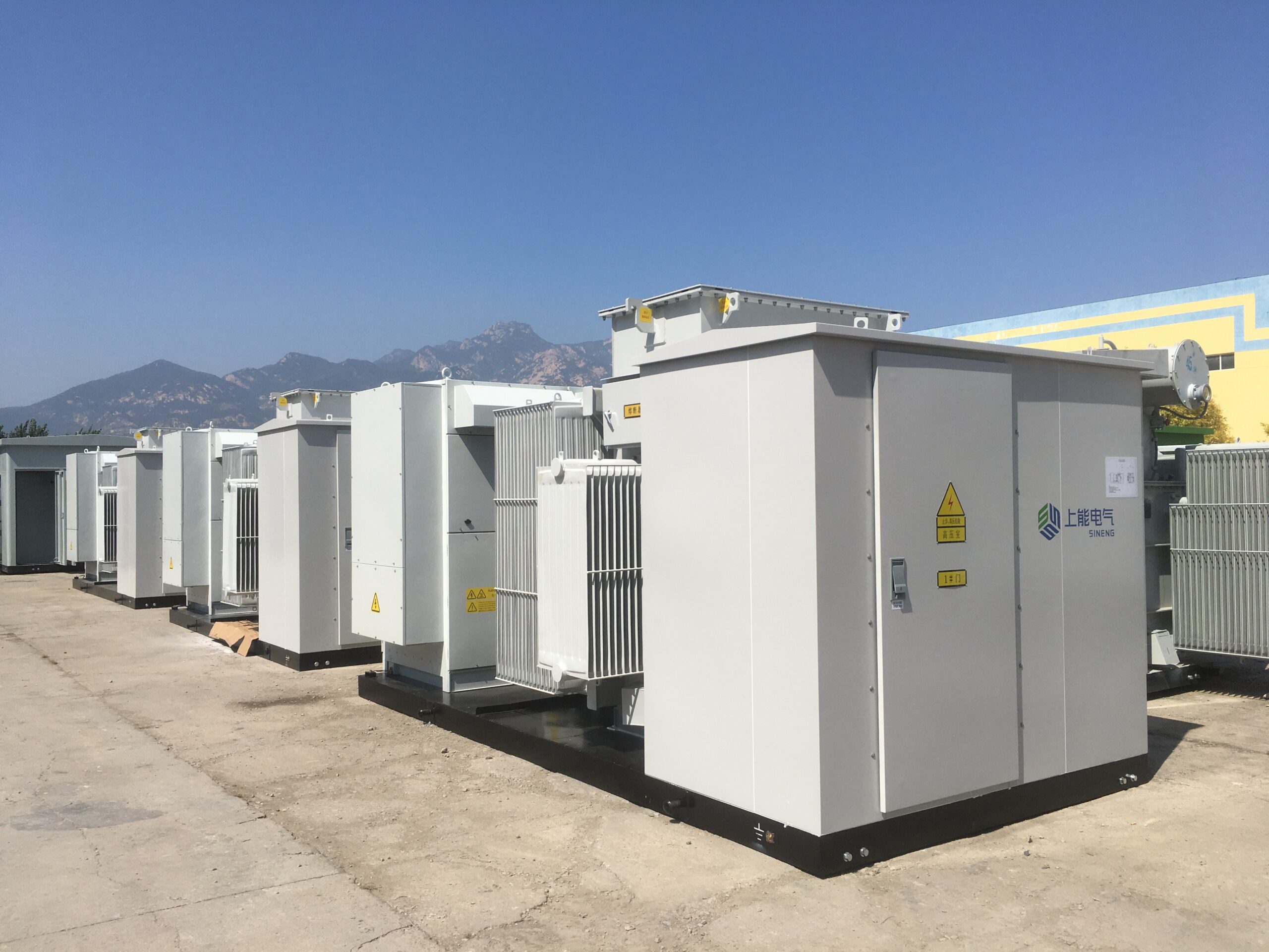
| Renewable Energy Sites | Step-up from inverter output | Pad-mounted or skid-mounted step-up |
Power Transformer in Action: Voltage Conversion Process
| Stage | Voltage Range | Transformer Function |
|---|---|---|
| Generation Plant | 11–25kV | Step-up to 132–765kV for transmission |
| High-Voltage Transmission Line | 132–765kV | Long-distance, low-loss energy transfer |
| Receiving Substation | 765kV → 132kV or 33kV | Step-down for regional distribution |
| Distribution Feeder Substation | 33kV → 11kV | Local grid voltage conversion |
| End-User Transformer | 11kV → 400V/230V | Residential and commercial power supply |
Without these transformers at each voltage step, the power system would either waste energy or be unsafe for equipment and people.
Power Transformer Types and Features
| Type | Use Case | Key Features |
|---|---|---|
| Two-Winding Transformer | General step-up/step-down use | High insulation between windings |
| Auto Transformer | HV interconnection between similar voltages | Compact and efficient |
| Dry-Type Transformer | Indoor or sensitive environments | Fire-resistant, low maintenance |
| K-Rated Transformer | Harmonic-rich environments like data centers | Withstands non-linear loads |
| Isolation Transformer | Hospitals, labs, telecom | Protects sensitive devices from surges |
Transformers are selected based on voltage, load type, location, environmental conditions, and required safety features.
Why Transformers Are Critical in These Locations
| Application | Why Transformers Are Needed |
|---|---|
| Long-Distance Transmission | To reduce current and minimize I²R losses |
| Urban Power Delivery | To reduce voltage for safe end-user operation |
| Industrial Machinery | To match equipment voltage and protect motors from damage |
| IT Infrastructure | To isolate and stabilize power for servers and storage systems |
| Healthcare Facilities | To prevent electrical noise and ensure uninterrupted equipment power |
Transformers also integrate with surge protectors, circuit breakers, and SCADA systems for complete operational control.
What Is a Distribution Transformer and How Does It Work?
Electricity generated at power stations travels a long journey before it reaches your home, office, or factory. After traveling through high-voltage transmission lines and being stepped down at substations, the final stage of voltage conversion is handled by a distribution transformer. These compact but essential devices are found on poles, underground vaults, or building basements—quietly working to provide safe, usable electricity to neighborhoods and businesses. This article explains what a distribution transformer is and how it works, highlighting its critical role in the power delivery process.
A distribution transformer is an electrical device that steps down medium-voltage electricity (typically 11kV or 33kV) from the distribution network to low-voltage levels (400V/230V) suitable for residential, commercial, and light industrial use. It works on the principle of electromagnetic induction, transferring electrical energy between windings to convert voltage safely and efficiently.
Distribution transformers are the last voltage-converting link in the electrical grid before electricity enters your building.
Distribution transformers convert medium-voltage electricity to low-voltage power for safe end-user consumption.True
They reduce 11kV or 33kV feeder voltage to 400V/230V for use in homes, businesses, and small industries.
Distribution transformers are used to increase voltage levels before power transmission.False
Voltage is stepped up at power generation using step-up transformers, while distribution transformers are used at the final step to reduce voltage.
Key Characteristics of Distribution Transformers
| Feature | Typical Specification |
|---|---|
| Input Voltage | 6.6kV / 11kV / 33kV |
| Output Voltage | 400V (three-phase) / 230V (single-phase) |
| Power Rating | 25 kVA to 2,500 kVA (typical range) |
| Mounting Type | Pole-mounted, pad-mounted, or substation |
| Cooling Method | Oil-immersed or dry-type |
| Transformer Type | Two-winding or three-phase |
These transformers are designed for high efficiency at low load variation, typically operating close to 24/7.
How Does a Distribution Transformer Work?
Working Principle: Electromagnetic Induction
- The primary winding is connected to the medium-voltage supply (e.g., 11kV).
- Alternating current in the primary creates a magnetic field in the laminated core.
- This field induces a voltage in the secondary winding, stepped down to 400V/230V.
- The voltage ratio depends on the number of turns in the primary vs. secondary windings.
Energy Transfer Process:
| Stage | Process Description |
|---|---|
| Medium-voltage power arrives | From 11kV feeder lines to the transformer’s primary terminals |
| Magnetic induction occurs | Magnetic flux links the windings in the iron core |
| Voltage is stepped down | Output from secondary winding matches building/appliance ratings |
| Low-voltage power is delivered | Through cables to residential or commercial customers |
A properly functioning distribution transformer ensures minimal energy loss and stable voltage output, even during load variation.
Types of Distribution Transformers
| Type | Description | Applications |
|---|---|---|
| Pole-Mounted | Mounted on utility poles, oil-filled, compact | Urban/rural overhead networks |
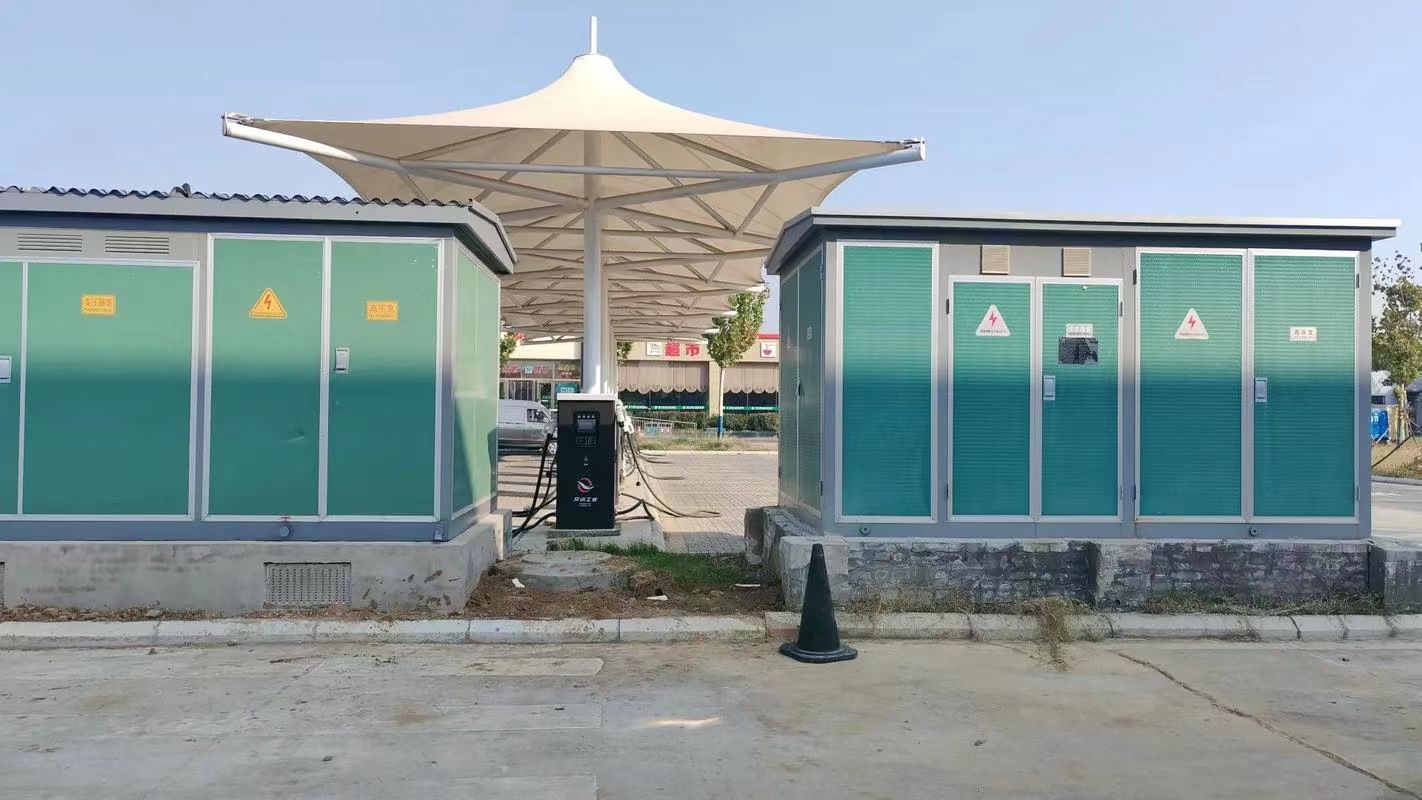
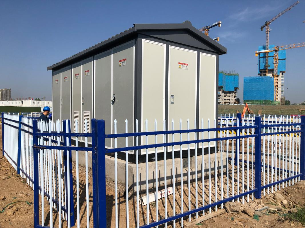
| Pad-Mounted | Ground-installed in locked enclosures | Suburban and commercial areas |
| Underground (Vault) | Installed below ground level with sealed enclosures | High-density urban areas |
| Dry-Type Transformer | Uses air or resin for cooling, no oil | Indoor or environmentally sensitive zones |
| Single-Phase Transformer | Serves small groups of homes | Rural or light residential applications |
| Three-Phase Transformer | Supplies commercial and industrial loads | Factories, apartment complexes |
Placement in the Electrical Power Chain
| Power System Stage | Voltage Level | Transformer Role |
|---|---|---|
| Generation Plant | 11–25kV | Step-up to 132–765kV for long-distance transmission |
| Transmission Substation | 765/400/220kV | Interconnects HV grids |
| Distribution Substation | 132kV → 33/11kV | Regional voltage conversion |
| Distribution Transformer | 11kV → 400V/230V | Final voltage reduction for end-user use |
Distribution transformers bridge the gap between the public grid and private power consumption.
Benefits of Distribution Transformers
| Benefit | Impact on Power Systems |
|---|---|
| Safe Voltage Supply | Prevents overvoltage damage to appliances and infrastructure |
| Reduced Transmission Losses | Supports short-distance low-voltage delivery |
| 24/7 Operation | Maintains grid continuity with minimal maintenance |
| Scalable | Easily deployed to new areas or growing load centers |
| Low Noise & High Efficiency | Designed to operate quietly with >98% energy efficiency |
Common Use Cases
| Application Area | Usage Role |
|---|---|
| Residential Neighborhoods | Supplies 230V to homes and street lighting |
| Commercial Zones | Feeds shops, restaurants, and offices at 400V |
| Small Industrial Plants | Provides 400V/690V for motors and control equipment |
| Hospitals and Schools | Delivers clean, uninterrupted low-voltage power |
| Remote Rural Areas | Pole-mounted units make decentralized electrification possible |
What Is an Instrument Transformer and Why Is It Important?
In modern power systems, accurate measurement and reliable protection are essential for safety, performance, and billing. But measuring and monitoring high voltages and currents directly in transmission or industrial environments would be impractical and dangerous. That’s where instrument transformers come in. These special-purpose transformers scale down current and voltage levels to safer, measurable values, enabling secure metering, control, and protective relay operation. This article explains what an instrument transformer is and why it is crucial for modern electrical infrastructure.
An instrument transformer is a precision transformer used to safely convert high voltage or high current in a power system to lower, standardized levels for measurement, monitoring, and protection. It allows instruments like voltmeters, ammeters, energy meters, and relays to operate accurately without direct connection to high-voltage lines.
They are vital for accurate billing, power system automation, and fault detection in both transmission and distribution networks.
Instrument transformers are used to scale down high voltages and currents to levels that can be safely measured and monitored.True
They enable protective relays, meters, and control systems to operate without direct exposure to hazardous voltages or currents.
Instrument transformers can be used to power household appliances directly from the transmission line.False
They are not designed to supply load power but only for accurate, safe measurement and protection.
Types of Instrument Transformers
| Type | Primary Function | Output Signal Type |
|---|---|---|
| Current Transformer (CT) | Converts high current to 5A or 1A | Secondary current proportional to load current |
| Voltage Transformer (VT/PT) | Converts high voltage to 110V or 100V | Secondary voltage proportional to system voltage |
| Combined Instrument Transformer | Integrates CT and VT in one unit | Used in compact or outdoor substations |
Instrument transformers are used in conjunction with protective relays, meters, and SCADA systems for real-time decision-making.
Working Principle
1. Current Transformer (CT)
- Primary winding carries full system current (e.g., 1,000A)
- Secondary winding delivers scaled current (e.g., 5A) to the meter or relay
- Secondary side must never be open-circuited due to high induced voltage risk
2. Voltage Transformer (VT/PT)
- Primary winding connects to high voltage (e.g., 11kV)
- Secondary winding provides reduced, stable voltage (e.g., 110V) to devices
- Offers galvanic isolation from high-voltage system
Where Instrument Transformers Are Used
| Location | Role of Instrument Transformers |
|---|---|
| Power Transmission Substations | Monitor voltage and current for high-voltage lines |
| Distribution Panels | Feed inputs to meters and relays in control rooms |
| Industrial Switchgear | Enable local load monitoring and overload protection |
| Utility Metering Points | Measure customer energy usage accurately for billing |
| Protection Schemes | Supply fault data to overcurrent, distance, and differential relays |
In protection applications, CTs and VTs are critical for detecting faults and triggering breaker operations in milliseconds.
Accuracy Classes and Standards
| Standard | Accuracy Class | Application |
|---|---|---|
| IEC 61869 / IEC 60044 | 0.2, 0.5, 1, 3, 5P, 10P | Class 0.2/0.5: Energy metering Class 5P/10P: Protection relays |
| IEEE C57.13 | C100, C200, etc. | Defines burden and accuracy for protection CTs |
| ANSI / NEMA | PT: 0.3 accuracy, 110V | Standardized VT outputs for control panels |
High-accuracy CTs and VTs ensure utility-grade energy accounting and reliable relay operation.
Advantages of Instrument Transformers
| Advantage | Impact |
|---|---|
| Safety | Protects meters and personnel from direct HV/HC exposure |
| Scalability | Allows integration of multiple meters and relays |
| Standardization | Provides consistent 5A/110V or 1A/100V outputs |
| Isolation | Electrically separates measurement circuits from power lines |
| Accuracy | Ensures billing precision and fault diagnosis |
Instrument transformers form the nervous system of power control and automation, delivering reliable data.
Example: CT & VT in Substation Protection
| System Voltage | Measured Current | Transformer Used | Secondary Output | Connected Devices |
|---|---|---|---|---|
| 132kV Busbar | 2,000A | CT (Ratio 400:5) | 5A | Overcurrent relay, energy meter |
| 132kV Line | 132kV | PT (Ratio 132kV:110V) | 110V | Distance relay, SCADA system, voltmeter |
This setup allows safe, high-fidelity monitoring and protection of vital infrastructure.
How Do These Three Transformer Types Differ in Design and Application?
Transformers are foundational components in electrical power systems, but not all transformers serve the same function. Understanding the differences between power transformers, distribution transformers, and instrument transformers is crucial for designing efficient, safe, and application-specific electrical infrastructure. Each transformer type has its own unique design characteristics, operational role, and application context—from high-voltage transmission and low-voltage distribution to precision measurement and protection.
Power, distribution, and instrument transformers differ primarily in their design purpose, voltage capacity, accuracy requirements, and location of use. Power transformers handle high-voltage energy transfer between generation and transmission systems; distribution transformers reduce voltage for end-user consumption; and instrument transformers convert high currents or voltages to measurable levels for monitoring and protection.
Each plays a specialized role to ensure the safe and efficient operation of the grid.
Power, distribution, and instrument transformers are used in different stages of the electrical system based on their design and function.True
Power transformers operate at high voltage and capacity; distribution transformers deliver low-voltage electricity; instrument transformers serve for measurement and protection.
All transformers are designed for voltage conversion only and are interchangeable.False
Instrument transformers are not used for power delivery, and each transformer type is optimized for a specific task.
Comparative Table: Design and Application Differences
| Attribute | Power Transformer | Distribution Transformer | Instrument Transformer |
|---|---|---|---|
| Primary Purpose | Voltage transformation for transmission | Voltage reduction for end-use distribution | Scaling voltage/current for measurement & protection |
| Typical Voltage Range | 132kV–765kV | 33kV / 11kV → 400V / 230V | Converts 132kV/11kV to 110V or 5A/1A |
| Installed At | Power stations, transmission substations | Near consumers, on poles or in pad enclosures | Switchgear, relays, metering panels |
| Core Design | Large core, high flux density | Smaller, designed for peak efficiency at lower loads | Precision-wound for accuracy |
| Load Behavior | Operates near full load continuously | Designed for variable, lower load profile | No power delivery—only signal output |
| Cooling Method | Oil-immersed (ONAN, ONAF) | Oil or air-cooled | Usually dry-type |
| Accuracy Requirement | Moderate (voltage regulation focus) | High efficiency, less critical accuracy | Very high (0.2%, 0.5%, 5P, 10P, etc.) |
| Standards Followed | IEC 60076, IEEE C57 | IEC 60076-6, ANSI C57.12 | IEC 61869, IEC 60044, IEEE C57.13 |
1. Power Transformer – For High-Voltage Energy Transfer
Design:
- Large oil-immersed units rated up to 1000 MVA
- Rugged insulation for very high voltage differentials
- Equipped with OLTC for dynamic voltage regulation
Application:
- Used at generation stations to step up voltage for long-distance transmission
- Located in HV and EHV substations to interconnect grid regions
Example:
- 400kV/220kV 315 MVA transformer at a transmission substation
2. Distribution Transformer – For Local Power Delivery
Design:
- Smaller footprint (typically 25 kVA – 2,500 kVA)
- Often pole-mounted or pad-mounted
- Designed to run at 70–90% load efficiency
Application:
- Final voltage reduction from 11kV to 400V / 230V for homes and businesses
- Found in urban and rural feeders, commercial complexes, and street corners
Example:
- 11kV / 415V, 250 kVA pole-mounted transformer feeding a residential block
3. Instrument Transformer – For Measurement and Protection
Types:
- Current Transformers (CTs): Convert high current (e.g., 1000A) to 5A/1A
- Voltage Transformers (VTs/PTs): Convert HV to standard voltages (e.g., 110V)
Design:
- Dry-type, sealed for safety
- High-precision accuracy classes (e.g., 0.2s, 5P20)
Application:
- Feed data to protective relays, energy meters, and SCADA systems
- Critical for fault detection, energy billing, and monitoring
Example:
- 132kV/110V VT used to power a distance relay in a protection panel
Visual Summary: Grid Location of Each Transformer Type
| Grid Stage | Transformer Type | Purpose |
|---|---|---|
| Power Generation | Power Transformer | Step-up to 400kV/765kV for transmission |
| Transmission Substation | Power Transformer / Auto Transformer | Interconnects high-voltage zones |
| Distribution Substation | Distribution Transformer | Step-down for local use |
| Feeder Pole or Pad Site | Distribution Transformer | Final voltage reduction for homes/buildings |
| Control Panel / Relay Room | Instrument Transformer (CT/VT) | Enables accurate and safe system monitoring |
What Are the Advantages and Limitations of Each Transformer Type?
Transformers are critical components that shape how electricity flows, is used, and is monitored across power systems. But no single transformer type fits every application—each is tailored for specific voltage levels, load behaviors, and system requirements. Whether you're transmitting energy across the country or monitoring it in a control room, understanding the advantages and limitations of power, distribution, and instrument transformers is essential for efficient and safe system design.
Power, distribution, and instrument transformers each offer unique advantages based on their intended function: power transformers are optimized for high-voltage bulk transfer, distribution transformers for local voltage adaptation and reliability, and instrument transformers for precise measurement and protection. However, each also comes with design and operational limitations that must be considered.
Using the right type in the wrong application leads to inefficiency, instability, or safety risks.
Each transformer type has specific advantages based on its design and application context, along with operational limitations.True
Power transformers suit high-load transmission, distribution transformers support local voltage delivery, and instrument transformers enable safe monitoring—but each has design constraints.
All transformers can be used interchangeably for voltage conversion, monitoring, and power delivery.False
Each transformer type is specialized; instrument transformers are not designed for power delivery, and power transformers cannot provide precision measurements.
Comparative Table: Advantages vs Limitations
| Transformer Type | Advantages | Limitations |
|---|---|---|
| Power Transformer | - High voltage handling (132–765kV) - High efficiency at full load - Durable for grid-scale use |
- Large, heavy, costly - Inefficient at partial loads - Needs complex cooling & insulation |
| Distribution Transformer | - Compact, easy to install - Good efficiency at partial load - Low maintenance |
- Limited voltage capacity (≤33kV) - Not suitable for bulk power transmission |
| Instrument Transformer | - Enables safe measurement of high V/I - Supports relay protection & metering - High accuracy classes |
- Not for power delivery - Requires correct burden/load match - Sensitive to saturation |
Each transformer is a fit-for-purpose component—optimized for system level, location, and electrical behavior.
1. Power Transformers: Bulk Energy Movers
✅ Advantages
- Operates efficiently at or near full load
- Supports very high MVA ratings (up to 1000 MVA+)
- Equipped with On-Load Tap Changers (OLTC) for real-time voltage regulation
- Ideal for interconnection of regions and large utility grids
⚠️ Limitations
- High initial cost and footprint
- Long lead time and specialized installation
- Cannot perform well under fluctuating or low-load conditions
- Requires cooling (oil or forced air/water) and periodic oil testing
Use When: You need to transmit or receive hundreds of megawatts over long distances
2. Distribution Transformers: Local Power Providers
✅ Advantages
- Flexible for installation (pole, pad, underground)
- High reliability with 24/7 unattended operation
- Tailored for medium voltage (11kV/33kV) step-down
- Low losses during part-load operation (60–80% load efficiency)
⚠️ Limitations
- Unsuitable for high-voltage switching or interconnection roles
- May overheat under heavy load without proper ventilation
- Not equipped with advanced monitoring unless custom-specified
- Basic units have no OLTC (only DETC or fixed ratio)
Use When: You need to deliver final voltage safely to homes, offices, or small factories
3. Instrument Transformers: Grid Sensors and Protectors
✅ Advantages
- Enables safe and accurate measurement of high-voltage or high-current circuits
- Critical for relay-based fault protection systems
- Provides galvanic isolation between HV system and control panels
- Supports compliance with metering accuracy standards (IEC, ANSI)
⚠️ Limitations
- Not designed for power transfer or energy delivery
- Can saturate under fault conditions if improperly sized
- Accuracy affected by temperature, frequency, and load mismatch
- Must never be open-circuited (CTs), or results in high voltage hazards
Use When: You need to monitor grid health, energy consumption, or implement fast protection schemes
Visual Use Case Summary
| Transformer | Installed At | Typical Applications |
|---|---|---|
| Power Transformer | Generation plant, HV substation | Voltage step-up/step-down for bulk energy transfer |
| Distribution Transformer | Feeder pole, pad mount, substation | Final voltage reduction to 400V/230V |
| Instrument Transformer | Relay panels, control rooms | Current/voltage monitoring for meters and relays |
Each type supports a distinct layer of the grid, from bulk transfer to precise sensing.
Key Considerations When Selecting
| Criteria | Best Choice |
|---|---|
| High load, long distance | Power Transformer |
| Urban/rural consumer supply | Distribution Transformer |
| Metering or relay support | Instrument Transformer |
| Compact indoor application | Dry-type Distribution or VT/CT |
| Harmonic-rich environment | K-rated Distribution Transformer or VT |
Always consult load profile, system voltage, safety, and environmental constraints before choosing.
How Do You Choose the Right Transformer Type for Your Needs?
Choosing the right transformer is not a one-size-fits-all decision. Whether you’re designing a utility substation, building a commercial facility, managing an industrial plant, or setting up a power monitoring system, the type of transformer you select directly affects efficiency, safety, reliability, and performance. The wrong choice can lead to power loss, equipment failure, or even hazards. That’s why it’s crucial to base your selection on key parameters like voltage level, power load, application purpose, and installation environment. In this article, we explain how to choose the right transformer type for your needs using real-world criteria and technical decision points.
To choose the right transformer type, determine your voltage conversion requirements, load characteristics (power rating, duty cycle), installation environment (indoor/outdoor), and application purpose (power delivery, voltage transformation, or measurement). Power transformers are best for high-voltage transmission, distribution transformers for localized voltage reduction, and instrument transformers for accurate monitoring and protection.
The right transformer enhances efficiency and safeguards your electrical infrastructure for the long term.
Selecting the correct transformer type requires evaluating voltage levels, load demand, environment, and intended function.True
Power, distribution, and instrument transformers each suit specific roles and must match the system’s technical and safety requirements.
Any transformer type can be used interchangeably as long as it connects to the grid.False
Each transformer is designed for a unique role—using the wrong type can result in equipment damage, inaccurate metering, or system failure.
Step-by-Step Guide to Choosing the Right Transformer
| Decision Factor | Considerations | Leads To |
|---|---|---|
| Voltage Levels | What voltage do you need to convert (e.g., 132kV to 11kV or 11kV to 400V)? | Power or distribution transformer |
| Power Rating (Load kVA/MVA) | How much power does your load require (e.g., 100 kW vs 50 MVA)? | Sizing the transformer |
| Application Purpose | Is the transformer for voltage conversion, load supply, or measurement/protection? | Power/distribution/instrument type |
| Environment | Indoor or outdoor? Hot/corrosive/dusty area? | Oil-immersed vs dry-type design |
| Safety Requirements | Do you need electrical isolation or protection from overcurrent/faults? | Instrument transformer needed |
| Regulatory Compliance | Do you need accuracy class metering (0.5, 0.2s) or fault detection? | CTs/VTs with specified classes |
| Future Expansion Plans | Will the load increase? Can the transformer be upgraded or paralleled? | Oversizing or modular configuration |
These steps ensure you're not only buying a transformer—but investing in system compatibility, scalability, and protection.
Comparison Table: Matching Transformer Types with Applications
| Application Scenario | Transformer Type Required | Typical Specs |
|---|---|---|
| Grid voltage interconnection | Power Transformer | 132/220/400kV, 100–1000 MVA |
| Supplying a residential block | Distribution Transformer | 11kV / 400V, 100–500 kVA |
| Monitoring current on a 132kV line | Instrument Transformer (CT) | 1000/5A, Accuracy 5P20 |
| Voltage measurement in a substation | Instrument Transformer (VT/PT) | 132kV / 110V, Class 0.5 |
| Data center energy supply | K-rated Distribution Transformer | 11kV / 400V, 500–1000 kVA, Harmonic resistant |
| High-rise commercial tower | Dry-type Distribution Transformer | 11kV / 400V, Fire-resistant, Compact |
| Wind/solar farm connection | Pad-mounted Power Transformer | 33kV → 132kV, 5–50 MVA |
| Relay protection for feeders | Protection-class CT and VT | CT: 400/5A, VT: 33kV / 110V, Class 5P10 |
Decision Tree: How to Select the Right Transformer
-
Is the goal to convert voltage for power delivery?
- Yes → Proceed to Step 2
- No → You're likely needing instrument transformers
-
What is your input/output voltage?
- High-to-high (e.g., 400kV ↔ 132kV) → Power Transformer
- Medium-to-low (e.g., 11kV → 400V) → Distribution Transformer
-
Is the power requirement > 2.5 MVA?
- Yes → Likely a Power Transformer
- No → Likely a Distribution Transformer
-
Is your installation space limited or indoor?
- Yes → Consider dry-type transformers
-
Do you need voltage or current readings for metering or protection?
- Yes → Use CTs (Current Transformers) and VTs/PTs (Voltage Transformers)
This approach filters transformer types by function, scale, and safety, ensuring proper selection.
Examples: Matching Use Case with Transformer
| Use Case | Correct Transformer | Why It’s Right |
|---|---|---|
| Interconnecting 400kV and 220kV grids | Power Transformer (400/220kV, 315 MVA) | Handles high MVA and voltage |
| Feeding a rural school | Pole-mounted Distribution Transformer | Compact and economical for low-load delivery |
| Fault relay on 11kV switchgear | CT (Ratio 300/5A), VT (11kV/110V) | Ensures relay trips correctly and safely |
| Commercial office tower | 11kV/400V Dry-Type Distribution Transformer | Fire-safe, low maintenance indoor unit |
Conclusion
The three main types of transformers—power transformers, distribution transformers, and instrument transformers—each serve distinct roles in the electrical system. Power transformers manage high-voltage transmission, distribution transformers deliver electricity to end users, and instrument transformers support measurement and protection. Together, they ensure the efficient and safe delivery of electricity from generation to consumption.
FAQ
Q1: What are the three types of transformers and their purposes?
A1: The three primary types of transformers are:
Power Transformers: Used in transmission networks to handle high voltages and large loads over long distances.
Distribution Transformers: Step down voltage for residential and commercial use at the final stage of the power supply chain.
Instrument Transformers: Used for measurement and protection; includes current transformers (CTs) and voltage transformers (VTs or PTs).
Q2: What is the role of a power transformer in the grid?
A2: Power transformers step up or step down voltage between generating stations and transmission networks. They operate at high voltages (≥33 kV) and are designed for maximum efficiency during constant, high-load operation.
Q3: How do distribution transformers differ from power transformers?
A3: Distribution transformers operate at lower voltages (typically <33 kV) and are used near end-users to convert voltage to usable levels (like 120/240V). They are built to handle fluctuating loads and are smaller in size than power transformers.
Q4: What are instrument transformers used for?
A4: Instrument transformers scale down high voltage or current to safe levels for use in metering and protection systems. CTs measure current, while PTs/VTs measure voltage—ensuring safe and accurate monitoring without direct contact with high-voltage systems.
Q5: Why is it important to understand different transformer types?
A5: Knowing the types of transformers helps:
Select the right equipment for voltage levels and system load
Ensure proper safety, efficiency, and grid reliability
Facilitate accurate measurement and effective fault protection
References
"Types of Transformers" – https://www.transformertech.com/types-of-transformers – Transformer Tech
"Power, Distribution & Instrument Transformers Explained" – https://www.electrical4u.com/types-of-transformers – Electrical4U
"Transformer Categories and Grid Applications" – https://www.powermag.com/transformer-categories – Power Magazine
"Instrument Transformer Functions and Standards" – https://www.sciencedirect.com/instrument-transformer-uses – ScienceDirect
"Smart Grid Guide: Transformer Integration" – https://www.smartgridnews.com/types-of-grid-transformers – Smart Grid News
"ResearchGate: Classification of Transformers" – https://www.researchgate.net/transformer-classification – ResearchGate
"Energy Central: Transformer Selection Guide" – https://www.energycentral.com/c/ee/transformer-selection – Energy Central
"PowerGrid: Key Transformer Types Used in the Grid" – https://www.powergrid.com/transformer-types-guide – PowerGrid