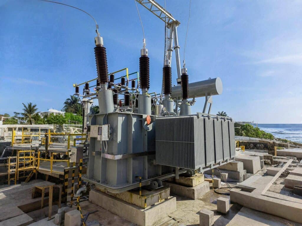
Radiators are essential cooling components used in oil-immersed transformers. As transformers operate under heavy electrical loads, they generate significant heat. Without effective cooling, internal components can overheat, leading to insulation breakdown, reduced efficiency, and even catastrophic failure. Radiators help dissipate this heat, ensuring that the transformer operates within safe thermal limits and maintains a long service life. This article explores how radiators function and why they are critical to transformer performance.
Why Do Transformers Need Cooling Systems?
Transformers are the unsung heroes of power systems, quietly stepping voltages up or down to enable efficient energy transmission and distribution. But in doing so, they face a significant physical challenge: heat generation. Without a proper cooling system, the intense heat produced during electrical operation can lead to insulation degradation, reduced lifespan, and even catastrophic failure. Unfortunately, this thermal issue is often underestimated by operators until performance drops or shutdowns occur. This article explains why transformers need cooling systems, how they work, and what happens when cooling is ignored or improperly managed.
Transformers need cooling systems because electrical energy losses within their windings and cores generate heat that must be dissipated to maintain safe operating temperatures. Effective cooling prevents overheating, preserves insulation integrity, maintains efficiency, ensures safety, and extends the operational life of the transformer. Without proper cooling, internal temperatures can exceed design limits, leading to accelerated aging, faults, or failure.
Transformer cooling is not just a technical feature—it’s a critical design and operational requirement directly tied to safety, capacity, and reliability.
Transformers can operate continuously without cooling systems.False
All transformers generate internal heat due to core and winding losses. Without cooling systems to dissipate this heat, the transformer would overheat, leading to insulation failure or fire hazards.
The Physics of Heat in Transformers
Every operating transformer experiences two primary forms of power loss:
| Loss Type | Cause | Heat Location |
|---|---|---|
| Core Losses | Hysteresis & eddy currents in magnetic core | Iron core (central area) |
| Copper Losses | I²R (resistive) losses in windings | Primary and secondary coils |
These losses are inevitable even in high-efficiency units. The resulting thermal energy raises the internal temperature of components beyond safe limits if not actively managed.
For instance, a 10 MVA transformer with 0.5% total losses dissipates 50 kW of heat—equivalent to 25 electric heaters running inside a sealed box.
What Happens Without Cooling?
If a transformer operates without an adequate cooling mechanism, the following risks emerge rapidly:
- Insulation breakdown: Each 10°C rise above design temp cuts insulation life in half (Arrhenius Law).
- Oil degradation: In oil-immersed units, overheating leads to oxidation, sludge, gas generation.
- Accelerated aging: Paper and varnish lose dielectric properties.
- Structural deformation: Prolonged heat causes coil displacement or tank warping.
- Fire risk: In severe cases, oil vapor ignites, leading to transformer explosions.
Heat is one of the primary causes of transformer failure in service.True
Excessive internal temperatures degrade insulation, reduce dielectric strength, and are directly linked to thermal faults, making heat a leading failure factor in transformers.
Core Components of Transformer Cooling Systems
| Component | Function |
|---|---|
| Cooling Medium | Carries heat away (air, oil, or synthetic fluid) |
| Radiators | Increases surface area for heat dissipation |
| Cooling Fans | Improves airflow over surfaces |
| Oil Pumps | Circulates fluid to accelerate cooling |
| Thermal Sensors | Monitors winding and top-oil temperatures |
| Heat Exchangers | Transfers heat to ambient via oil/air or oil/water |
These elements work together to form a closed thermal management system designed to hold operating temperatures below critical thresholds under load.
Cooling Methods Defined by Standards
IEEE/ANSI and IEC categorize transformer cooling using standard notations:
| Code | Cooling Type | Used In |
|---|---|---|
| ONAN | Oil Natural, Air Natural | Distribution transformers |
| ONAF | Oil Natural, Air Forced (fans) | Power transformers |
| OFAF | Oil Forced, Air Forced | High-capacity units |
| OFWF | Oil Forced, Water Forced | Coastal/indoor HV substations |
| KNAN | Synthetic ester cooled | Fire-sensitive areas |
| AN/AF | Air Natural / Air Forced (dry-type) | Indoor transformers |
Each cooling class defines how heat is removed, and more complex systems allow higher load ratings (or overloading under controlled conditions).
Transformer Cooling and Load Capacity
Cooling capability directly affects how much power a transformer can safely carry:
- Better cooling → higher capacity
- Effective thermal control → longer life
| Cooling Class | Load Factor (approx.) | Common Application |
|---|---|---|
| ONAN | 100% | General power distribution |
| ONAF | 120–140% | Industrial power systems |
| OFAF | 150–160% | Substations, heavy industry |
| Dry-Type (AF) | 110–120% | Hospitals, buildings, indoors |
According to IEEE C57.91, transformer loading guidelines vary based on ambient temperature, cooling design, and expected duration of overload.
Upgrading the cooling system can increase a transformer's load-handling capacity.True
By adding fans or pumps, thermal dissipation is enhanced, allowing the transformer to safely operate under higher loads without exceeding temperature limits.
Real-World Illustration: Cooling Failure Case Study
Situation:
A 20 MVA ONAF transformer at a steel plant experienced repeated relay trips and overheating alarms.
Investigation:
- Cooling fans were non-functional due to controller fault.
- Ambient temperature in the substation exceeded 45°C.
- Top oil temp reached 105°C under nominal load.
Outcome:
- Transformer derated to 15 MVA to prevent damage.
- Emergency repair restored fan logic.
- Load returned to 20 MVA after cooling restored.
Lesson: Cooling system failures directly impact transformer availability and capacity.
What Are Transformer Radiators and How Do They Work?

Transformers perform essential voltage conversion tasks in electrical systems, but in doing so, they produce heat due to core and copper losses. This heat must be effectively removed to prevent damage to insulation, loss of efficiency, or complete failure of the unit. One of the most critical components for thermal management in oil-immersed transformers is the radiator. However, this system is often overlooked or misunderstood, leading to poor maintenance or incorrect design decisions. In this article, we’ll examine what transformer radiators are, how they function, and why they are vital for safe and efficient transformer operation.
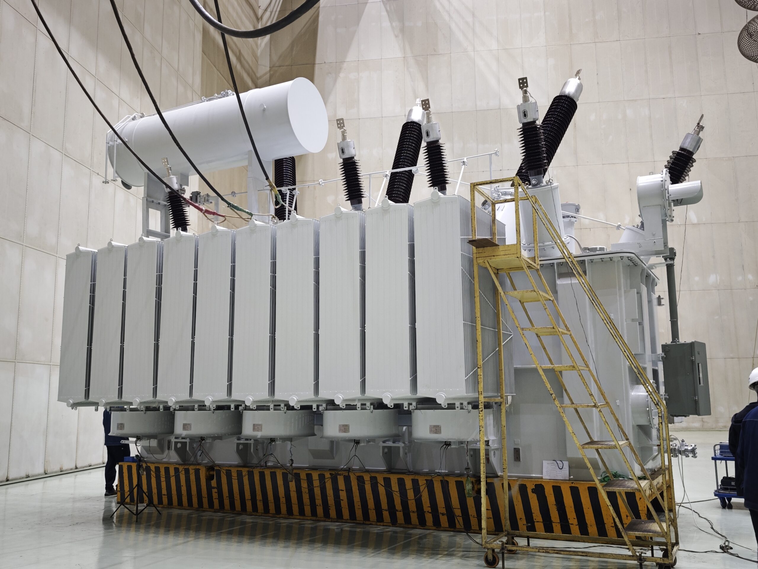
Transformer radiators are external cooling devices attached to oil-immersed transformers that dissipate heat generated during operation. They work by allowing hot insulating oil to flow through finned metal panels, where heat is transferred to the surrounding air. This process can occur naturally (via convection) or be assisted by fans to increase airflow and cooling efficiency. Transformer radiators are essential for maintaining safe internal temperatures and supporting higher load conditions.
Without radiators, most oil-filled transformers would quickly overheat under normal operating conditions, leading to insulation degradation and reduced service life.
Transformer radiators play a minor role in cooling and can be omitted in large units.False
Radiators are critical components for heat removal in oil-immersed transformers. Larger units require even more extensive radiator systems to manage high thermal loads.
Purpose and Importance of Radiators
Transformer operation produces internal losses:
| Type of Loss | Source | Location |
|---|---|---|
| Core Loss | Hysteresis and eddy currents in the core | Magnetic core area |
| Copper Loss | I²R losses in windings | Transformer windings |
These losses turn into heat, which increases internal oil and winding temperatures. Overheating beyond design limits can cause:
- Insulation breakdown
- Oil oxidation and sludge formation
- Accelerated aging of components
- Short-circuit faults or fire risks
Radiators are therefore indispensable in heat management, especially in high-capacity transformers used in substations, industrial facilities, and power generation systems.
How Transformer Radiators Work
Transformer radiators operate on thermal convection principles, where heat is transferred from the transformer's hot oil to the cooler ambient air.
- Hot oil rises from the transformer’s core into the top of the radiator via connecting pipes.
- Oil circulates downward through radiator fins or tubes, transferring heat to the metal surfaces.
- Air cools the outer surface of the radiator either naturally or through forced ventilation.
- Cooled oil returns to the transformer tank through the bottom header.
This continuous oil flow cycle helps regulate the internal temperature during transformer operation.
Types of Cooling Methods Using Radiators
| Cooling Type | Oil Movement | Air Movement | Typical Application |
|---|---|---|---|
| ONAN | Natural convection | Natural convection | Distribution and small power units |
| ONAF | Natural convection | Forced by fans | Medium and large power transformers |
| OFAF | Forced by pumps | Forced by fans | High-power and substation units |
| OFWF | Forced by pumps | Forced water flow | Urban, coastal, or indoor environments |
ONAN (Oil Natural, Air Natural)
- Simple, passive cooling
- Depends on natural oil and air circulation
- Limited cooling capacity
ONAF (Oil Natural, Air Forced)
- Adds cooling fans to increase air velocity over radiators
- Enables transformers to operate at higher loads
OFAF (Oil Forced, Air Forced)
- Uses pumps to circulate oil
- Fans further boost air cooling
- Ideal for large units requiring high-capacity cooling
Transformer Radiator Components
| Component | Function |
|---|---|
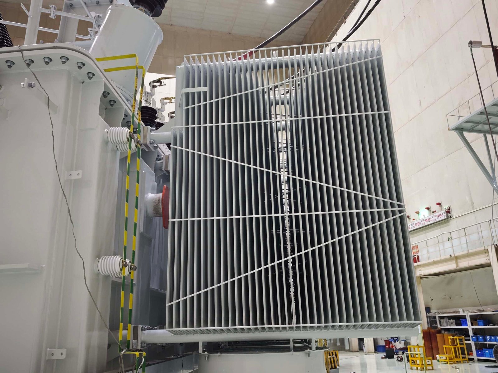
| Radiator Panels | Thin steel fins or tubes that carry oil and release heat |
| Header Pipes | Distribute oil between transformer tank and radiators |
| Inlet/Outlet Valves | Allow radiator isolation for maintenance |
| Cooling Fans | Increase airflow over radiator surfaces |
| Temperature Sensors | Monitor top oil or winding temperature for fan control |
Radiators are typically made from carbon steel, and the surface is treated with anti-corrosion coatings. Fans are installed with automatic control systems that activate based on temperature thresholds.
Effectiveness of Radiator Systems
Radiators increase the cooling surface area significantly. A typical medium-size transformer with six radiator banks and four fans can increase its loading capacity by over 30% when switching from ONAN to ONAF mode.
| Mode | Cooling Capacity | Load Handling Increase |
|---|---|---|
| ONAN | 100% | Base design load |
| ONAF | 125–140% | 25–40% above ONAN |
| OFAF | 150–160% | 50–60% above ONAN |
This increased thermal margin is especially important during high demand periods or emergency loading conditions.
Upgrading a transformer with fan-assisted radiators can extend its load capacity.True
By enhancing the cooling performance with fans, transformers can handle higher loads without exceeding temperature limits. This allows temporary or continuous loading beyond base ratings.
Design and Sizing Considerations
When designing or selecting transformer radiators, engineers must evaluate:
- Total power loss to be dissipated (in kW)
- Ambient air temperature and airflow patterns
- Oil flow rate and viscosity
- Radiator surface area required for heat exchange
- Space availability and mounting orientation
- Environmental factors (corrosion, dust, humidity)
Some radiator designs are modular and can be detached for transport or maintenance. Others are fully welded to the tank for compactness.
Maintenance of Radiator Systems
Proper functioning of transformer radiators depends on routine inspection and servicing:
| Task | Interval | Purpose |
|---|---|---|
| Fan testing | Monthly | Ensure cooling activation at temperature rise |
| Visual leak inspection | Weekly | Detect oil leaks that reduce coolant level |
| Cleaning of fins | Bi-annually | Remove dust that insulates radiator surface |
| Valve function check | Annually | Confirm oil flow control and isolation ability |
| Thermal imaging | Quarterly | Identify blocked or uneven radiator sections |
Failure to maintain the radiator system may result in silent overheating and undetected performance degradation.
What Are the Types of Transformer Radiator Cooling Methods (ONAN, ONAF, OFAF, etc.)?

As transformers operate, they continuously generate heat from electrical losses in their windings and cores. This heat must be managed efficiently to prevent insulation failure, minimize aging, and maintain operational integrity. For oil-immersed transformers, radiator-based cooling systems are the primary method of heat dissipation. These systems vary based on how oil and air are circulated to remove heat. Understanding the different cooling methods—ONAN, ONAF, OFAF, OFWF, and others—is essential for proper transformer design, application, and maintenance.
Transformer radiator cooling methods include ONAN (Oil Natural Air Natural), ONAF (Oil Natural Air Forced), OFAF (Oil Forced Air Forced), and OFWF (Oil Forced Water Forced). These methods differ in how the insulating oil and surrounding medium (air or water) are circulated to remove heat. The choice of method depends on transformer size, location, ambient conditions, and required load capacity.
Each cooling system directly affects the transformer's thermal performance, loading capability, and efficiency.
All radiator-cooled transformers use the same cooling principle regardless of size.False
Radiator-cooled transformers use different methods of oil and air movement depending on capacity and application. ONAN is suitable for smaller units, while OFAF and OFWF are needed for high-capacity transformers.
Comparative Table: Transformer Radiator Cooling Methods
| Cooling Method | Oil Flow | Air/Water Flow | Cooling Type | Application |
|---|---|---|---|---|
| ONAN | Natural | Natural | Passive | Distribution & small power transformers |
| ONAF | Natural | Forced (fans) | Semi-active | Medium transformers, peak load control |
| OFAF | Forced (pumps) | Forced (fans) | Fully active | Large substations, industrial systems |
| OFWF | Forced (pumps) | Forced (water coolers) | Fully active | Enclosed or coastal installations |
| KNAN | Natural | Natural | Passive (with ester fluid) | Indoor/fire-sensitive areas |
1. ONAN – Oil Natural, Air Natural
- Oil circulates due to thermal convection
- Air cools the radiator fins naturally
- No fans or pumps
- Simple, maintenance-free design
Used in:
- Distribution transformers
- Small- to mid-sized substations
- Transformers under 2.5 MVA typically
Advantages:
- Low operational cost
- Silent operation
- Reliable under moderate loads
Limitations:
- Limited cooling capacity
- Cannot support extended overloading
2. ONAF – Oil Natural, Air Forced
- Oil movement remains natural (by heat-induced flow)
- Air movement is enhanced by external fans
- Fans switch on when temperature rises beyond thresholds
Used in:
- Transformers from 2.5 MVA to 25 MVA
- Industrial applications requiring flexible loading
- Transformers with dual cooling ratings (e.g., 16/20 MVA)
Advantages:
- Enhanced cooling compared to ONAN
- Increases loading by 25–40%
- Allows controlled overload operation
Limitations:
- Requires fan maintenance and power supply
- Slightly higher noise levels
ONAF cooling allows transformers to operate above their ONAN-rated load for extended periods.True
ONAF systems use fans to increase air flow across radiators, improving cooling efficiency and enabling the transformer to handle higher loads temporarily.
3. OFAF – Oil Forced, Air Forced
- Oil is circulated using electric pumps
- Air is pushed across radiators by fans
- Provides consistent, high-capacity cooling
Used in:
- Transformers above 25–30 MVA
- Power stations, utility substations
- Transformers with high fault-level exposure
Advantages:
- Precise thermal control
- Maximizes transformer capacity
- Ideal for fluctuating load conditions
Limitations:
- Complex system with multiple failure points
- Requires backup power for pumps/fans
- Higher maintenance cost
4. OFWF – Oil Forced, Water Forced
- Oil is pumped through external oil-to-water heat exchangers
- Water absorbs heat and is cooled via radiators or a cooling tower
- Ideal for restricted-air environments (e.g., indoor, tunnels)
Used in:
- Urban installations
- Hydro power stations
- Transformer rooms with poor ventilation
Advantages:
- Silent, compact, and efficient cooling
- Suitable for environments where air cooling is limited
Limitations:
- Requires water treatment and circulation systems
- More expensive to install and maintain
OFAF and OFWF systems are necessary for high-capacity transformers that operate in demanding environments.True
Large transformers generate high thermal loads that cannot be dissipated by natural convection. Forced systems like OFAF and OFWF ensure safe operation and extended lifespan.
5. KNAN – K-Class Oil Natural, Air Natural
- Similar to ONAN, but uses natural ester or synthetic insulating fluid
- Designed for fire-sensitive or environmentally restricted zones
Used in:
- Hospitals, schools, tunnels, buildings
- Indoor installations requiring fire safety
Advantages:
- Fire-resistant cooling fluid
- Environmentally biodegradable
- Suitable for confined spaces
Limitations:
- Limited to small- to mid-size transformers
- Ester fluids are costlier than mineral oil
Load Capacity Comparison by Cooling Type
| Cooling Method | Relative Capacity | Typical Use Case |
|---|---|---|
| ONAN | 100% | Base-rated operation |
| ONAF | 125–140% | Occasional or continuous overload |
| OFAF | 150–160% | Heavy industry or utility applications |
| OFWF | 150%+ | Urban indoor installations |
| KNAN | 100% | Indoor, low-risk environments |
Selection Criteria for Cooling Methods
| Factor | ONAN | ONAF | OFAF | OFWF | KNAN |
|---|---|---|---|---|---|
| Transformer size | Low | Medium | Large | Large | Low |
| Load variability | Low | Medium | High | High | Low |
| Environmental noise limit | Good | Moderate | Low | Good | Excellent |
| Maintenance complexity | Low | Medium | High | High | Medium |
| Fire safety requirement | Low | Low | Medium | High | Very High |
| Installation space limit | Large | Medium | Medium | Small | Small |
How Are Radiators Connected to the Transformer Tank?
Transformer radiators are essential for dissipating heat from oil-immersed transformers, especially under continuous or heavy loads. However, their performance and serviceability heavily depend on how they are connected to the transformer tank. Improper connections can cause flow restriction, oil leakage, or even thermal imbalance. Many operators overlook this vital mechanical and hydraulic interface, resulting in maintenance difficulties or system inefficiencies. This article explores how transformer radiators are connected to the tank, what components are involved, and how proper connection design ensures safe operation and ease of servicing.
Transformer radiators are connected to the main tank via top and bottom oil headers or flanged nozzles that allow hot oil to flow out into the radiators and cooled oil to return. These connections include shut-off valves, gaskets, and bolted flanges to enable oil circulation, isolate radiators during maintenance, and ensure leak-proof operation. The connection system supports natural or forced oil flow depending on the cooling method used.
Well-engineered radiator connections are critical to maintaining proper oil flow rates, achieving thermal performance, and enabling field maintenance without draining the entire tank.
Radiators are welded permanently to the transformer and cannot be removed.False
Most transformer radiators are connected using flanged joints or removable manifolds, allowing for maintenance, repair, or replacement without draining the entire oil volume.
Basic Flow Path: From Tank to Radiator and Back
The cooling oil inside an oil-immersed transformer follows this path:
- Hot oil rises due to heat from the core and windings.
- It exits the main tank through the top radiator connection.
- The oil flows down through the radiator panels or fins.
- As it cools, it returns to the transformer via the bottom radiator connection.
- The cycle continues naturally (ONAN) or is accelerated by pumps (OFAF).
This process depends on continuous and unrestricted flow between the transformer tank and radiator elements.
Key Components of Radiator-to-Tank Connections
| Component | Function |
|---|---|
| Flanged Headers | Securely connect radiator pipes to tank openings |
| Inlet/Outlet Ports | Entry and exit points for oil circulation |
| Shut-off Valves | Isolate radiator from tank for service |
| Gaskets | Provide oil-tight seal between flange surfaces |
| Drain Plugs | Allow localized draining of radiator units |
| Vent Valves | Release trapped air during oil filling |
| Bolted Fasteners | Hold radiator flanges securely to tank with uniform pressure distribution |
Connection Types Explained
1. Flanged Pipe Connections
- Most common method
- Steel pipe with ANSI-standard or custom flange
- Includes gasket and bolted ring to prevent leaks
- Easy to disconnect for maintenance
2. Manifold Headers
- Radiators connect to a horizontal header pipe
- Header is bolted to the tank
- Radiators are connected to the header via branch pipes
- Efficient for transformers with multiple radiators
3. Threaded Couplings (Small Transformers)
- Used in compact distribution transformers
- Screw-type or socket-type threaded connections
- Limited to small radiators and low oil flow
4. Welded (Permanent) Connections
- Rare in modern units
- Found in older or compact designs
- Difficult to service or replace without cutting
Transformer radiator headers often include shut-off valves for isolation.True
Shut-off valves are integrated into the radiator piping or header to allow removal or maintenance without draining the transformer.
Shut-Off Valves and Their Importance
| Valve Type | Location | Purpose |
|---|---|---|
| Butterfly Valve | Between tank and radiator | Quick shut-off and full bore oil flow |
| Gate Valve | Inline with oil ports | Precise control, common in larger connections |
| Ball Valve | Smaller connections | Compact and easy to operate |
| Check Valve | In OFAF systems | Prevents backflow of oil when pump is off |
Benefits of shut-off valves:
- Enable radiator maintenance without draining the full tank
- Allow replacement of a single damaged radiator
- Simplify oil filling, venting, or leak repair
- Provide modular control in multiple-radiator systems
Installation and Maintenance Considerations
Alignment
Flanges must align precisely to avoid oil flow restriction or mechanical stress.Torque Balance
Flange bolts must be tightened in a cross-pattern to ensure even pressure and gasket compression.Leak Testing
Pressure testing or thermal scanning should be used after installation to confirm seal integrity.Seal Material
Gasket material should be compatible with transformer oil and withstand thermal expansion.Corrosion Protection
Connection points are painted or galvanized to prevent rust, especially in outdoor or coastal environments.
Radiator Replacement or Removal Procedure (Typical Steps)
- Deactivate transformer and allow cooling.
- Close top and bottom shut-off valves to isolate radiator.
- Open vent plug to release pressure.
- Use drain plug to remove oil from the radiator.
- Unbolt flange connection from the tank.
- Detach radiator from mounting brackets and remove.
- Install replacement using new gaskets, ensure torque and alignment.
- Reopen valves, refill oil, vent air, and test for leaks.
Always follow manufacturer-specific procedures and safety protocols during disconnection.
Radiators can be removed and replaced without draining the entire transformer oil.True
With the use of shut-off valves and proper flange isolation, individual radiators can be removed for maintenance without requiring full oil drainage.
Real-World Example: 10 MVA Transformer with 6 Radiators
- Each radiator connected via top and bottom flanged pipes
- Includes butterfly valves at both ends for isolation
- Replaced one radiator after corrosion without opening the tank
- Used infrared imaging to confirm leak-free operation after reinstallation
Result: Transformer returned to service within 24 hours without full oil handling
What Maintenance Do Transformer Radiators Require?
Transformer radiators play a vital role in regulating the operating temperature of oil-immersed transformers, especially those with medium to high ratings. Despite their passive appearance, radiators are active heat exchange systems that depend on proper oil circulation, airflow, and mechanical integrity. However, when maintenance is neglected, the cooling performance of radiators drops sharply—resulting in overheating, insulation breakdown, or emergency shutdowns. This article outlines the essential maintenance practices for transformer radiators to ensure they continue functioning efficiently throughout the transformer's life cycle.
Transformer radiator maintenance involves regular inspection, cleaning, leak detection, thermal scanning, fan testing, valve operation checks, and monitoring oil circulation. These activities ensure optimal heat dissipation, prevent failures, and extend the transformer's service life. Maintenance should be preventive and scheduled based on operational environment, transformer loading, and manufacturer recommendations.
Well-maintained radiators keep oil temperatures under control, reduce aging rates, and allow for overload flexibility without risking system failure.
Transformer radiators require no regular maintenance once installed.False
Radiators must be inspected, cleaned, and tested regularly to ensure proper heat transfer, oil flow, and mechanical integrity. Neglecting radiator maintenance can lead to cooling failure and transformer overheating.
Key Maintenance Tasks for Transformer Radiators
| Maintenance Task | Frequency | Purpose |
|---|---|---|
| Visual Inspection | Monthly | Detect oil leaks, rust, or physical damage |
| Cleaning Radiator Fins | Semi-annually | Remove dust or debris that impairs heat dissipation |
| Fan Operation Testing | Monthly (ONAF/OFAF) | Verify fan start-up at correct temperature |
| Leak Testing and Sealing | Quarterly | Prevent oil loss and moisture ingress |
| Valve Operation Check | Annually | Ensure shut-off valves open and close properly |
| Oil Circulation Verification | Annually | Confirm oil is flowing correctly through radiators |
| Thermal Imaging | Quarterly | Identify blocked or underperforming radiator sections |
| Bolt and Flange Tightening | Annually | Maintain mechanical seal integrity |
| Radiator Replacement | As Needed | Replace corroded, leaking, or damaged radiator panels |
1. Visual Inspection and Leak Detection
Inspect all radiators for:
- Oil leaks at flanged joints, gaskets, or welds
- Rust, bulging, or denting on radiator fins or tanks
- Paint degradation, which can lead to corrosion
- Signs of overheating, such as discoloration
Look under the radiators for oil spots or pooling, and monitor oil level gauges to detect slow leaks.
Tip: Use UV oil dye or fluorescent leak detectors for non-visible leak sources.
Oil leaks from transformer radiators can lead to insulation failure.True
Loss of insulating oil reduces cooling effectiveness and dielectric strength, increasing the risk of winding insulation breakdown or fire.
2. Radiator Surface Cleaning
Dust, leaves, bird droppings, and industrial contaminants reduce the radiator’s surface efficiency. Cleaning can be done using:
| Method | Equipment | Notes |
|---|---|---|
| Air Blower | Portable compressor + nozzle | Suitable for dry environments |
| Water Jetting | Low-pressure hose or washer | Avoid high pressure to prevent fin damage |
| Brush Cleaning | Soft-bristle brush | Manual, safe for delicate surfaces |
Clean between fins to ensure unobstructed airflow. In coastal or polluted environments, increase cleaning frequency.
3. Fan and Motor Testing (ONAF and OFAF Systems)
For radiators with fans:
- Check fan motor alignment, belt tension (if applicable), and blade integrity
- Ensure automatic fan control activates at the correct oil temperature
- Clean air intake screens and filters
- Measure amp draw to detect motor overload or imbalance
Log fan start/stop operations and replace faulty thermal sensors or relays promptly.
| Checkpoint | Parameter |
|---|---|
| Fan motor voltage | Match to rated supply |
| Vibration level | Should be minimal |
| Rotation direction | Confirm proper airflow path |
4. Valve Functionality and Oil Flow Monitoring
Shut-off valves must:
- Open and close fully without sticking
- Be free of leaks at the stem or seals
- Be operated at least once a year to prevent seizing
Oil flow can be monitored using:
- Sight glasses
- Temperature gradient measurement (inlet vs outlet)
- Infrared thermography
Uneven temperature patterns often indicate:
- Blocked radiator section
- Trapped air
- Sludge accumulation
5. Thermal Imaging for Proactive Fault Detection
Use an infrared camera to scan radiator surfaces during operation:
| Condition | Interpretation |
|---|---|
| Uniform cooling | Normal operation |
| One section significantly hotter | Flow blockage or fan failure |
| Cooler than normal section | Airflow obstruction or overcooling fans |
| Isolated hot spot | Internal sludge or fin blockage |
Record thermal profiles quarterly to identify trends or degradation over time.
Infrared thermal imaging helps detect blocked radiator sections before they cause failure.True
Thermal imaging reveals temperature distribution across radiator surfaces, allowing early identification of flow blockages or cooling inefficiencies.
6. Mechanical Fasteners and Sealing Systems
Bolts on radiator flanges, mounting brackets, and fan housings must be tightened according to torque specifications. Gaskets at flanged connections should be checked for:
- Oil weeping or saturation
- Cracking or hardening due to aging
- Loss of compression over time
Use OEM-recommended gasket material during replacements, compatible with transformer oil and temperature cycles.
7. When to Replace a Radiator
Radiator replacement is necessary when:
- Severe corrosion compromises structural integrity
- Persistent leaks cannot be sealed
- Fan housings are damaged beyond repair
- Blockages due to internal sludge are irreversible
Replacement procedure typically involves:
- Isolating the radiator via shut-off valves
- Draining radiator oil and safely removing the unit
- Installing new radiator with fresh gaskets
- Refilling and venting trapped air during commissioning
Maintenance Frequency Matrix
| Environment | Inspection | Cleaning | Fan Check | Thermal Scan | Valve Check |
|---|---|---|---|---|---|
| Urban/Indoor | Monthly | Bi-Annually | Monthly | Quarterly | Annually |
| Industrial/Outdoor | Monthly | Quarterly | Monthly | Quarterly | Annually |
| Coastal/Marine | Bi-Monthly | Monthly | Monthly | Bi-Monthly | Annually |
| Desert/Dusty | Monthly | Monthly | Monthly | Monthly | Annually |
What Are the Design Considerations for Radiators in Transformers?
Radiators are not merely bolt-on accessories for transformers—they are integral to the transformer's cooling system and must be precisely engineered to ensure the unit can dissipate heat effectively under full load. However, many procurement and design teams overlook critical aspects like oil dynamics, heat transfer rates, mounting configurations, and environmental exposure. Poor radiator design can lead to overheating, unnecessary derating, or premature failure. In this article, we will explore the essential design considerations when selecting or engineering transformer radiators for both new and retrofit applications.
Transformer radiator design must consider cooling capacity (based on thermal losses), oil flow dynamics, radiator surface area, material selection, connection type, mounting configuration, environmental exposure, and integration with auxiliary cooling components like fans or pumps. Each parameter must be engineered to match the transformer's size, voltage class, ambient conditions, and operational duty cycle.
Neglecting proper design standards can lead to thermal inefficiencies, accelerated insulation aging, and even catastrophic failure in high-load or high-temperature environments.
Radiator design has minimal impact on transformer performance.False
Radiator design directly affects a transformer's thermal management. Inadequate radiator sizing or poor airflow handling can result in overheating and significantly reduce transformer lifespan.
Key Design Parameters for Transformer Radiators
| Design Factor | Description |
|---|---|
| Heat Dissipation Requirement | Based on transformer losses (core + copper losses in kW) |
| Surface Area | Determines heat transfer to ambient air |
| Oil Flow Path & Rate | Natural convection vs. forced circulation |
| Cooling Class Compatibility | ONAN, ONAF, OFAF, OFWF—drives structural and performance features |
| Material & Coating | Steel, aluminum, paint thickness, corrosion resistance |
| Connection Type | Flanged, manifold, welded—affects serviceability and sealing integrity |
| Mounting Design | Vertical, side-mounted, bolt-on, bracketed, skid-based |
| Auxiliary Cooling Elements | Fans, sensors, valves, thermostats for active systems |
| Environmental Resistance | Dust, salt, humidity, UV exposure |
1. Thermal Load and Surface Area Calculation
Transformer radiators must be designed to dissipate the total thermal loss generated during normal and peak operation.
Example:
For a 10 MVA transformer with:
- Core loss = 6.5 kW
- Winding loss = 22.5 kW
- Total heat to dissipate = 29 kW
Radiator design then follows this equation:
Q = A × U × ΔT
Where:
- Q = heat to be dissipated (W)
- A = effective radiator surface area (m²)
- U = overall heat transfer coefficient (W/m²·K)
- ΔT = temperature difference between oil and ambient air
From this, the required radiator surface area can be determined.
| Transformer Rating | Typical Radiator Surface Area |
|---|---|
| 2.5 MVA | \~6–10 m² |
| 10 MVA | \~25–30 m² |
| 50 MVA | 100+ m² |
2. Oil Flow Configuration
| Cooling Type | Oil Flow | Air Flow | Notes |
|---|---|---|---|
| ONAN | Natural | Natural | Passive system, relies on thermal gradients |
| ONAF | Natural | Forced | Requires fans for increased airflow |
| OFAF | Forced | Forced | Oil pumps + fans for maximum efficiency |
| OFWF | Forced | Water cooled | For space-limited or enclosed indoor environments |
The radiator must be designed to match the oil flow pattern:
- Use baffles or internal guides for uniform oil distribution
- Consider inlet and outlet positioning for optimal convection
- Size header pipes appropriately to prevent flow restriction
Oil flow through radiator panels is passive in all transformer types.False
While natural circulation is used in ONAN/ONAF systems, OFAF and OFWF cooling require forced oil flow through pumps to maintain thermal equilibrium.
3. Radiator Panel Design and Configuration
| Panel Shape | Description | Common Use Case |
|---|---|---|
| Corrugated fins | Compact, integrated with tank | Distribution transformers |
| Detachable panels | Modular, bolted to tank | Power transformers ≥ 5 MVA |
| Tubular fins | Vertical tubes, high surface exposure | OFAF systems with high loads |
| Flanged banks | Include top and bottom headers | Multiple panel configurations |
Best practices:
- Minimize dead zones or air pockets in panel design
- Standardize panel sizes for spares and maintenance
- Include vent plugs and drain valves per panel
4. Material Selection and Coating Systems
Most transformer radiators are fabricated from:
- Carbon steel: Affordable, strong, easy to weld
- Aluminum: Lightweight, corrosion-resistant, used in coastal environments
Surface treatment includes:
- Zinc-rich primers
- Polyurethane or epoxy coatings
- Anti-corrosion topcoat systems
| Environment | Recommended Coating Thickness (μm) |
|---|---|
| Normal outdoor | 80–100 |
| Industrial | 120–150 |
| Marine/coastal | 160–200 |
5. Mounting and Connection Considerations
| Mounting Type | Advantages | Notes |
|---|---|---|
| Bolt-on vertical | Easy to install, good airflow | Needs robust support brackets |
| Manifold header | Simplifies multiple radiator setup | Often used in large power transformers |
| Welded (permanent) | Compact design | Limited to small transformers, hard to replace |
| Skid-mount modules | Pre-assembled units | Useful for modular installations |
Connection types:
- Top and bottom oil ports with flanges and gaskets
- Shut-off valves for isolation
- Fan mounting frames if ONAF or OFAF
Ensure mechanical integrity under thermal expansion and seismic load conditions.
6. Integration of Auxiliary Components
| Component | Purpose |
|---|---|
| Cooling fans | Increase airflow across fins (ONAF/OFAF) |
| Thermostats | Trigger fans based on oil temperature |
| Pressure relief | Prevent overpressure in sealed systems |
| Oil level sensor | Monitor radiator oil fill during service |
| Fan guards | Ensure personnel safety |
7. Environmental and Climatic Considerations
Transformers deployed in harsh climates must have radiators designed for:
- High UV resistance (desert, tropical)
- Salt spray protection (marine/coastal)
- Heavy dust protection (mining, arid zones)
- Ice/snow load considerations (cold climates)
Radiator louvers or shutters may be used in cold environments to retain heat during low load or startup conditions.
Radiator design must consider environmental exposure for long-term durability.True
Temperature extremes, moisture, dust, salt, and sunlight degrade radiator materials and coatings, making environmental compatibility a critical design factor.
Sample Technical Specification Table
| Parameter | Value Example for 16 MVA Transformer |
|---|---|
| Total Losses | 45 kW |
| Cooling Type | ONAN/ONAF |
| Radiator Type | Detachable panel type |
| Number of Panels | 8 |
| Total Surface Area | 35 m² |
| Material | Hot-rolled carbon steel |
| Coating System | 3-layer epoxy, 150 μm total |
| Air Flow (ONAF) | 4800 m³/h per fan |
| Oil Inlet/Outlet Flange | DN80 with gasketed bolting |
| Mounting | Vertical, side-mounted |
| Accessories | Fan bracket, drain valve, air plug |
Conclusion
Radiators play a vital role in regulating the temperature of oil-immersed transformers by enabling effective heat exchange between the transformer oil and ambient air. Their design and performance directly affect the transformer's reliability, efficiency, and lifespan. Proper selection, installation, and maintenance of radiators are critical for ensuring transformers can operate safely under varied electrical loads and environmental conditions. Without radiators, thermal stress could lead to frequent failures and high maintenance costs.
FAQ
Q1: What is the function of radiators in transformers?
A1: Radiators in transformers serve as heat exchangers that help cool down the hot insulating oil. As the transformer operates, electrical losses generate heat. This heat is transferred to the oil, which circulates through radiators. The large surface area of the radiator allows heat to dissipate into the surrounding air, maintaining a safe internal temperature and preventing insulation failure or component damage.
Q2: How do transformer radiators work?
A2: Radiators are typically attached to the main tank of the transformer. Here's how they work:
Hot oil rises to the top and enters the radiator
It flows through metal fins or pipes exposed to ambient air
Heat transfers from oil to air, cooling the oil
The cooled oil re-enters the transformer at the bottom
This process may be natural (ONAN) or assisted with fans or pumps (ONAF, ODAF) depending on the cooling method used.
Q3: What types of transformer radiators exist?
A3: Common radiator types include:
Panel-type radiators: Flat and compact, used in small to medium transformers
Tubular radiators: Made of vertically arranged tubes with high surface area
Finned radiators: Include external fins to increase heat dissipation
Forced-air-cooled radiators: Equipped with fans to improve air circulation and cooling efficiency
Each type is selected based on transformer size, location, and cooling requirement.
Q4: Why is radiator maintenance important for transformers?
A4: Radiators play a critical role in preventing overheating. Poor maintenance can lead to:
Oil leakage at joints or valves
Air blockage due to dirt, dust, or debris
Fan failure in forced cooling systems
Corrosion reducing thermal performance
Regular cleaning, inspection, and oil monitoring are essential to ensure the transformer operates safely and efficiently.
Q5: Can radiator systems be upgraded or retrofitted?
A5: Yes. Transformer radiators can be upgraded to improve cooling performance, especially in:
Aging units needing capacity increase
Harsh environments where dust or ambient temperature impairs cooling
Upgrades may include:
Fan installation or replacement
High-efficiency radiators with improved materials
Remote thermal monitoring systems
This helps optimize transformer reliability, load capacity, and life extension.
References
Electrical4U – Cooling of Transformers
https://www.electrical4u.com/cooling-of-transformer/
IEEE C57.12.00 – General Requirements for Transformers
https://standards.ieee.org/standard/C57_12_00-2015.html
Doble Engineering – Thermal Monitoring in Transformers
https://www.doble.com/solutions/temperature-and-cooling/
ScienceDirect – Advanced Cooling Systems for Transformers
https://www.sciencedirect.com/science/article/pii/S135943111831012X