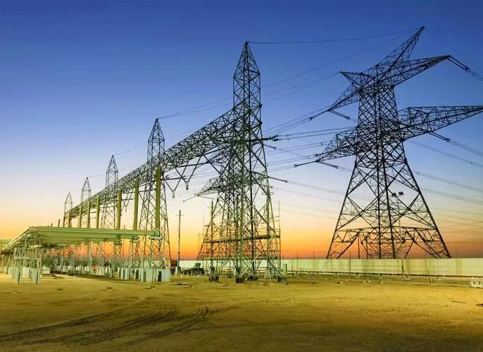
Selecting the right transformer involves a number of technical considerations, but voltage level is one of the most critical. The voltage level of the power system determines the insulation design, cooling method, core size, and overall construction of the transformer. Mismatched transformer selection can lead to inefficiency, overheating, or even failure. This article explains the relationship between system voltage levels and how they influence transformer selection, ensuring that power distribution is both safe and efficient.
Why Is Voltage Level Important in Transformer Selection?
Choosing the wrong transformer voltage level can lead to underperformance, overload, insulation failure, and ultimately, a costly mismatch between your power needs and the grid. Whether for an industrial plant, utility substation, or renewable energy site, voltage level is the first and most crucial parameter in transformer selection. Transformers are specifically engineered to operate within a defined voltage range—any deviation compromises performance, efficiency, and safety.
Voltage level is critical in transformer selection because it determines the appropriate transformer rating, insulation requirements, size, cost, and compatibility with the power system. Matching the primary and secondary voltage levels to the supply and load ensures efficient power transfer, proper insulation coordination, and compliance with grid or equipment voltage classes.
This article explains how transformer voltage levels affect design, functionality, and system integration—and why getting it right is essential to both performance and protection.
Transformer voltage mismatch can cause efficiency loss, overheating, and equipment damage.True
A transformer with incorrect voltage levels can over- or under-supply connected equipment, leading to faults or performance degradation.
Voltage level has no effect on the transformer's insulation or physical size.False
Higher voltage levels require more insulation, larger creepage distances, and larger core and winding dimensions.
Understanding Transformer Voltage Ratings
A transformer's voltage rating includes:
- Primary voltage (HV side) – connected to the source (e.g., grid, generator)
- Secondary voltage (LV side) – connected to the load (e.g., plant, feeder)
Nameplate Example:
Transformer Rating: 33/0.415 kV, 2500 kVA
- Primary: 33,000 V
- Secondary: 415 V
- Rated for stepping down MV grid voltage to industrial LV level
Why Voltage Level Matters in Transformer Selection
1. System Compatibility
- Transformer must match incoming supply voltage and load voltage requirements
-
Voltage mismatch results in:
- Under-voltage (insufficient power delivery)
- Over-voltage (damaged equipment or protection trips)
| Scenario | Result |
|---|---|
| 11 kV transformer connected to 33 kV grid | Explosive overvoltage damage |
| 33 kV transformer feeding 11 kV load | Load won’t function (under-voltage) |
2. Insulation Coordination
-
Higher voltage = greater insulation requirements:
- More oil or air gap
- Larger bushing clearance
- Higher Basic Insulation Level (BIL)
- BIL must exceed expected system surges
| Voltage Level | Typical BIL (kV) | Implication for Design |
|---|---|---|
| 11 kV | 95 | Lower insulation cost |
| 66 kV | 325–350 | Requires larger oil volume |
| 132 kV | 550 | Larger tank, extended clearances |
3. Size, Weight, and Cost
-
Voltage level directly impacts transformer size:
- Higher voltage = more windings, more core insulation, larger tank
-
Also affects:
- Transportation cost
- Foundation strength
- Installation complexity
| Voltage Level | Approx. Weight (Dry) | Footprint (m²) | Relative Cost |
|---|---|---|---|
| 11/0.4 kV | 1–2 tons | 1–1.5 m² | Low |
| 33/11 kV | 4–6 tons | 3–5 m² | Moderate |
| 132/33 kV | 25–40 tons | 8–12 m² | High |
4. Regulatory Compliance and Grid Code Requirements
-
Utilities and regional operators often specify:
- Approved voltage classes (e.g., 11, 33, 66, 132 kV)
- Voltage tolerances (±5%, ±10%)
- Phase displacement and earthing method based on voltage
-
Selecting incorrect voltage:
- Voids grid connection permits
- Requires expensive redesign or rejection
5. System Load and Voltage Drop Consideration
- Long-distance transmission causes voltage drop
- Higher voltage = lower current = reduced transmission loss
- Step-up transformers used at generation; step-down at load centers
| Distance | Preferred Voltage Level |
|---|---|
| <500 m (industrial) | 415 V or 11 kV |
| 0.5–10 km | 33 kV |
| >10 km | 66/132/220 kV |
Practical Selection Table by Application
| Application | Typical Voltage Level | Transformer Type |
|---|---|---|
| Residential complex | 11/0.4 kV | Oil-immersed distribution |
| Industrial substation | 33/11 kV | 3-phase step-down, ONAN |
| Grid substation | 132/33 kV | Power transformer with OLTC |
| Solar farm export | 33/0.6 kV or 66/0.6 kV | Inverter-duty transformer |
| Wind farm connection | 132/33 kV or 220/33 kV | High-voltage step-up transformer |
Voltage Level and Protection Coordination
- Surge arresters, relays, and CTs must match the voltage level
- Protection settings (e.g., 87T, 50/51, 64R) rely on expected voltage magnitude
- Voltage mismatch disrupts fault detection and can disable relay tripping
| Voltage Input to Relay | Outcome |
|---|---|
| Correct (e.g., 11 kV) | Normal operation |
| Under/Over voltage | Relay trip, miscoordination |
How Are Voltage Ratings Classified in Power Systems?
Power systems operate across a wide range of voltages—from household circuits to high-voltage transmission lines. To standardize electrical infrastructure, safety requirements, and equipment specifications globally, voltage ratings are classified into distinct categories. These classifications define how power is generated, transmitted, distributed, and used—affecting transformer design, insulation levels, switchgear types, and regulatory compliance.
Voltage ratings in power systems are classified into standard levels such as Low Voltage (LV), Medium Voltage (MV), High Voltage (HV), Extra High Voltage (EHV), and Ultra High Voltage (UHV), each defined by specific voltage ranges. These categories ensure compatibility of equipment, guide protection system design, and provide a basis for safety and operational standards in power infrastructure.
Understanding these voltage categories is essential for engineers, operators, and facility planners involved in transformer selection, network design, and utility coordination.
Voltage classifications are universally standardized and used to guide equipment design and insulation levels.True
Standards from IEC and IEEE define clear voltage boundaries that determine how equipment is rated and used within the electrical grid.
There is no operational difference between low, medium, and high voltage systems in practice.False
Each voltage class dictates different equipment types, insulation methods, safety rules, and usage scenarios.
Standard Voltage Classification According to IEC and IEEE
| Voltage Classification | IEC Range (RMS) | IEEE/NEMA Range | Typical Applications |
|---|---|---|---|
| Low Voltage (LV) | ≤ 1,000 V | ≤ 1,000 V | Residential, commercial wiring |
| Medium Voltage (MV) | 1 kV to 35 kV | 1 kV to 69 kV | Industrial supply, distribution lines |
| High Voltage (HV) | 36 kV to 230 kV | 69 kV to 230 kV | Sub-transmission, inter-substation |
| Extra High Voltage (EHV) | 230 kV to 800 kV | 230 kV to 800 kV | Long-distance transmission |
| Ultra High Voltage (UHV) | >800 kV | >800 kV | Intercontinental grids (rare) |
Note: Exact ranges may slightly differ by region. For example, some utilities consider 66 kV as MV, others as HV depending on national grid codes.
Why Voltage Classification Matters
1. Equipment Design
- Transformers, switchgear, cables, insulators, and protection relays are designed based on voltage class
-
Each class has:
- Different insulation levels (e.g., Basic Insulation Level or BIL)
- Required creepage distances
- Rated short-circuit withstands
| Voltage Class | BIL Example (kV peak) | Insulator Design |
|---|---|---|
| LV | \~5 kV | Plastic or resin-molded |
| MV (11 kV) | \~75–95 kV | Oil-paper, epoxy bushings |
| HV (132 kV) | \~550 kV | Porcelain or polymer |
2. Safety and Regulatory Compliance
- Each voltage level has its own operational and safety protocols
-
Requirements differ in:
- Minimum clearance
- Arc-flash PPE
- Grounding design
- Installation procedures
| Voltage Class | Arc Flash Category | Minimum Clearance (Air) |
|---|---|---|
| LV | Cat 0–2 | 10–30 mm |
| MV | Cat 3–4 | 300–500 mm |
| HV | Special risk PPE | >1000 mm |
3. System Planning and Grid Architecture
-
Voltage class affects:
- Where substations are placed
- How transformers step up or down voltage
- What line distances are viable
- Transmission typically uses EHV/UHV; distribution uses MV/LV
| Power System Segment | Typical Voltage Class | Description |
|---|---|---|
| Generation Step-Up | HV to EHV (132–400 kV) | Power station to transmission grid |
| Bulk Transmission | EHV/UHV (220–765 kV) | Cross-region or national backbone |
| Sub-Transmission | HV (66–132 kV) | Between transmission and distribution |
| Distribution Primary | MV (11–33 kV) | Feeds industrial/commercial areas |
| Distribution Secondary | LV (400/230 V) | Final delivery to end-users |
Transformer Voltage Ratings and Class Compatibility
When selecting transformers, the voltage class guides:
- Core and coil design
- Insulation thickness and oil gaps
- Bushing type and arrester coordination
| Transformer Type | Voltage Class | Example Rating |
|---|---|---|
| Distribution Transformer | LV/MV | 11/0.415 kV |
| Substation Transformer | MV/HV | 66/11 kV |
| Power Transformer | HV/EHV | 132/33 kV, 220/66 kV |
International Voltage Class Comparison Table
| Country/Region | Common MV | Common HV | Common EHV |
|---|---|---|---|
| USA (ANSI/IEEE) | 4.16, 13.8, 34.5 kV | 69, 115, 230 kV | 345, 500, 765 kV |
| EU (IEC) | 10, 11, 20, 33 kV | 66, 110, 132, 220 kV | 400, 500, 765 kV |
| India | 11, 22, 33 kV | 66, 132, 220 kV | 400, 765 kV |
| China | 10, 35 kV | 110, 220 kV | 500, 800 kV (UHVDC) |
| Japan | 6.6, 22 kV | 66, 154, 275 kV | 500, 1000 kV |
What Types of Transformers Are Used for Different Voltage Levels?
In electrical power systems, no single transformer type fits all voltage scenarios. The voltage level determines not only the transformer’s size and insulation requirements, but also its core construction, cooling method, winding configuration, and application. Whether stepping voltage down for home appliances or stepping it up for cross-country transmission, choosing the right transformer type for the voltage level is essential for efficiency, safety, and long-term system reliability.
Different types of transformers are used for different voltage levels: Low Voltage (LV) distribution transformers serve residential or commercial areas; Medium Voltage (MV) transformers support industrial loads and local substations; High Voltage (HV) and Extra High Voltage (EHV) transformers are designed for transmission and grid interconnection. Each type is engineered with specific insulation, cooling, and mechanical features tailored to its voltage class and application.
This article presents a professional, application-based breakdown of transformer types according to their voltage levels, usage environments, and technical design characteristics.
Only one type of transformer is used across all voltage levels.False
Transformers are specifically designed and classified based on voltage levels—each application demands different insulation, winding, and cooling strategies.
EHV transformers require larger insulation clearance and special construction compared to LV transformers.True
EHV transformers must withstand higher electric fields, requiring enhanced insulation design, larger bushings, and more robust construction.
Classification of Transformer Types by Voltage Level
| Voltage Class | Voltage Range | Typical Transformer Type | Primary Applications |
|---|---|---|---|
| Low Voltage (LV) | ≤ 1,000 V | Distribution Transformer | Residential & commercial supply |
| Medium Voltage (MV) | 1 kV – 35/66 kV | Power or Dry-Type Transformer | Industrial feeders, substations |
| High Voltage (HV) | 66 kV – 230 kV | Power Transformer with OLTC | Substations, regional transmission |
| Extra High Voltage (EHV) | 230 kV – 800 kV | Autotransformer or Intertie | Long-distance grid transmission |
| Ultra High Voltage (UHV) | >800 kV | EHVDC/UHVAC Transformer | Intercontinental HVDC networks |
1. Low Voltage Transformers (LV ≤ 1,000 V)
Common Types:
- Pole-mounted Distribution Transformers
- Pad-mounted Transformers
- Dry-Type Encapsulated Transformers
Design Characteristics:
- Compact size (1–5 tons)
- Air or oil cooled (AN/ONAN)
- Standard ratings: 11/0.415 kV, 6.6/0.415 kV
Applications:
- Residential housing
- Commercial buildings
- Small industries
| Transformer Type | Use Case | Cooling Type | Mounting |
|---|---|---|---|
| Pole-mounted | Overhead line transformers | ONAN | Overhead |
| Pad-mounted | Urban/commercial installations | ONAN | Ground |
| Dry-type (encapsulated) | Indoor, fire-sensitive areas | AN | Indoor wall/floor |
2. Medium Voltage Transformers (1 kV – 66 kV)
Common Types:
- MV Distribution Transformers
- Compact Substation Transformers
- Cast Resin (Dry-Type) Transformers
Design Characteristics:
- Used in secondary substations (33/11 kV, 22/6.6 kV)
- Often include on-load tap changers (OLTC)
- Oil-immersed or dry-type based on fire risk
Applications:
- Urban substations
- Renewable energy interfaces
- Industrial loads
| Transformer Rating | Voltage Example | Cooling | Typical Installation |
|---|---|---|---|
| 2 MVA, 11/0.4 kV | Distribution networks | ONAN | Indoor/outdoor |
| 6 MVA, 33/11 kV | Sub-transmission | ONAN/ONAF | Outdoor on plinth |
| 3 MVA, 22/0.415 kV | Solar/wind projects | Cast resin | Enclosed room |
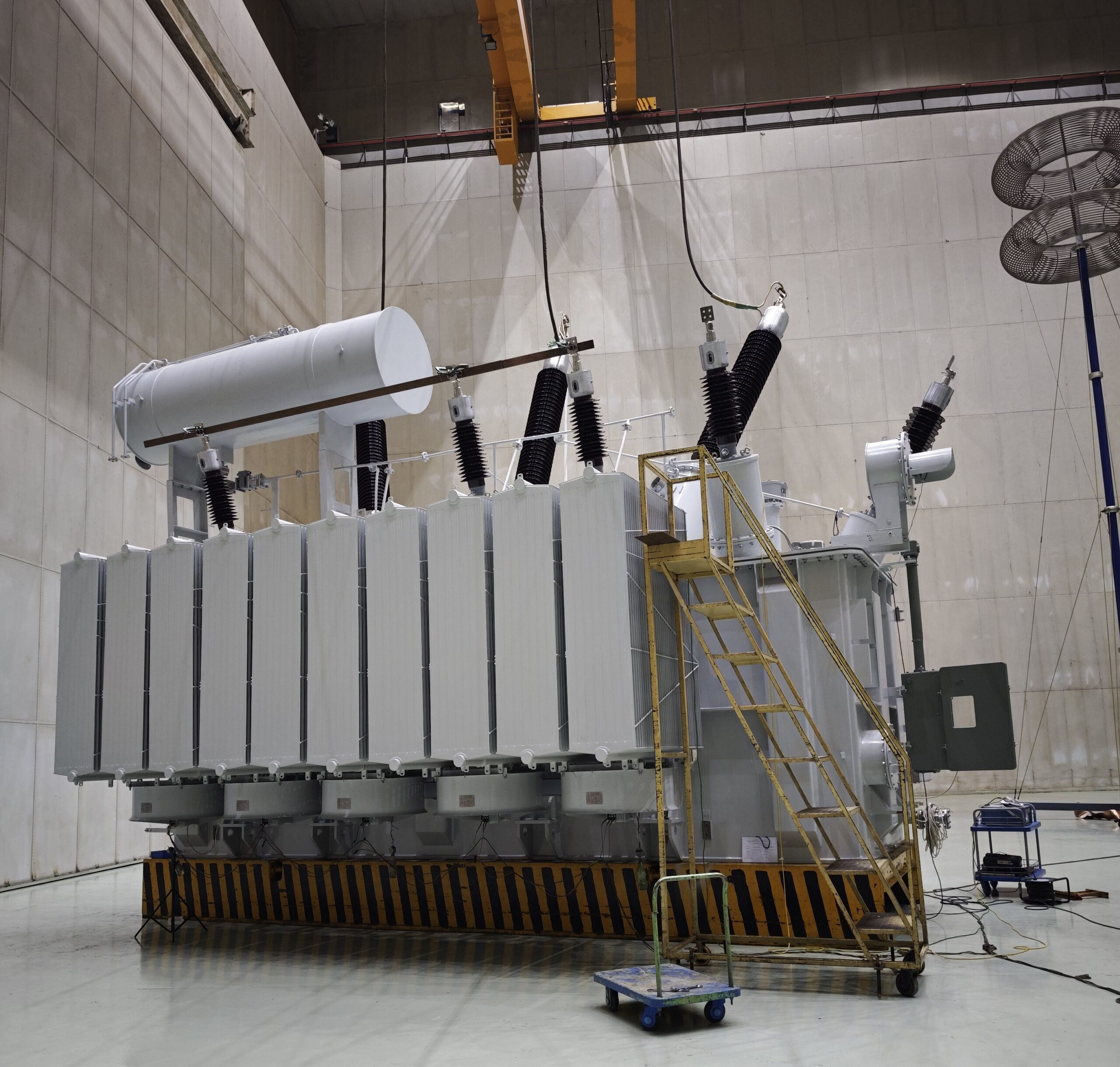
3. High Voltage Transformers (66 kV – 230 kV)
Common Types:
- Grid-Tie Power Transformers
- Step-Up Generator Transformers
- Three-Winding Transformers
Design Characteristics:
- Large oil-immersed units (30–100+ tons)
-
Equipped with:
- OLTC (±10–15% regulation)
- Bushings rated for high BIL
- Radiators or fans for cooling (ONAF)
Applications:
- Substation interconnection
- Grid-tie for generation stations
- Transmission voltage regulation
| Type | Rating Example | Feature Highlight |
|---|---|---|
| Power Transformer | 132/33 kV, 25 MVA | Tap changer + surge arresters |
| Generator Transformer | 11/132 kV, 40 MVA | Generator protection class |
| Auto Transformer | 220/132 kV, 100 MVA | Three-winding system |
4. Extra High Voltage (EHV) Transformers (230–800 kV)
Common Types:
- Bulk Power Autotransformers
- Intertie Step-Up/Down Transformers
- EHV Converter Transformers (for HVDC)
Design Characteristics:
- Weigh up to 300 tons
- Require multiple bushings, cooling banks
- Include oil pumps, fans, OLTCs, Buchholz relays
- BIL rating up to 1800 kV
Applications:
- Backbone transmission grid
- Regional interconnections
- National grid stabilization
| Type | Voltage Rating | Cooling | Special Features |
|---|---|---|---|
| EHV Autotransformer | 400/220 kV, 250 MVA | OFAF | OLTC + forced cooling |
| Intertie Unit | 400/132/66 kV, 3-winding | ONAN/ONAF | Parallel operation support |
| HVDC Transformer | ±500 kV DC link | ONAF/ODAF | Valve winding insulation |
5. Ultra High Voltage (UHV >800 kV)
Common Types:
- UHVAC Interconnection Transformers
- UHVDC Converter Transformers
Design Characteristics:
- Custom engineered for 1000 kV+
- Composite bushings, gas-insulated interfaces
- Installed in limited sites (e.g., China, India, Brazil)
Applications:
- Cross-continent HVDC lines
- National power balancing stations
| Project Example | Type | Voltage Rating |
|---|---|---|
| China SGCC HVDC link | UHVDC Converter Transformer | ±1100 kV |
| India 1200 kV Test Line | UHVAC Transformer | 1200/400 kV |
Summary Table: Transformer Types by Voltage Level
| Voltage Class | Typical Ratings | Common Transformer Types | Key Use Cases |
|---|---|---|---|
| LV | ≤ 1 kV | Distribution, dry-type, pole-mounted | End-user supply, commercial buildings |
| MV | 1 kV – 66 kV | Pad-mounted, substation, dry-type | Distribution substations, renewables |
| HV | 66 – 230 kV | Grid power transformers | Substation and grid interconnection |
| EHV | 230 – 800 kV | Bulk step-up/down, autotransformer | National transmission infrastructure |
| UHV | >800 kV | Converter and UHVAC transformers | Continental HVDC/UHVAC transmission |
How Does Voltage Affect Insulation and Safety Design?
The higher the voltage, the greater the electrical stress placed on equipment—and the more critical insulation and safety measures become. Power transformers and associated systems are designed to withstand specific voltage levels without failure. If insulation design is inadequate or safety protocols are not voltage-appropriate, the result can be dielectric breakdown, flashover, arcing, and catastrophic equipment failure. Thus, voltage is not just a performance parameter—it is a fundamental driver of insulation thickness, air clearance, creepage distance, and safety margins.
Voltage directly affects insulation and safety design by determining the required insulation type and thickness, minimum electrical clearances, material dielectric strength, and protective device coordination. Higher voltages demand enhanced insulation systems, greater physical separation, and stricter safety zones to prevent arcing, flashover, and personnel hazards.
This article explains how increasing system voltage changes the way transformers and switchgear must be insulated and protected—and why these design considerations are vital for safety and operational reliability.
Higher voltage systems require greater air clearance and insulation levels to prevent breakdown.True
As voltage increases, the potential for electrical arcing and insulation failure rises, requiring greater distances and stronger materials to withstand the electric field.
Insulation and safety design are the same for 11 kV and 220 kV transformers.False
Insulation and clearance requirements scale significantly with voltage, and higher-voltage transformers need enhanced insulation schemes, bushing sizes, and physical separations.
1. How Voltage Determines Insulation Design
A. Dielectric Strength Requirements
- Voltage stress increases with system voltage → requires stronger insulating materials
-
Insulation design must resist:
- AC dielectric stress
- Switching surges
- Lightning impulses
B. Types of Insulation Affected
- Winding insulation (paper-oil, resin)
- Bushing insulation (porcelain, composite, SF₆)
- Core-to-coil insulation
- Air gaps between energized and grounded parts
| System Voltage | BIL (kV Peak) | Insulation Type |
|---|---|---|
| 11 kV | 95 | Oil-paper, solid bushings |
| 66 kV | 325–350 | Oil-immersed, extended bushings |
| 132 kV | 550 | Composite or gas-insulated bushings |
| 400 kV | 1300–1550 | Pressboard, SF₆, large air gaps |
2. Creepage and Clearance Requirements by Voltage
A. Creepage Distance
- The shortest distance along the surface of insulation
- Increases to prevent surface tracking due to pollution and moisture
B. Clearance Distance
- The shortest air gap between live and earthed parts
- Prevents flashover during overvoltage events
| Voltage Level | Creepage (mm/kV) | Phase-to-Ground Clearance (mm) |
|---|---|---|
| 11 kV | 25–30 | \~150–200 |
| 66 kV | 30–40 | \~600–800 |
| 132 kV | 35–45 | \~1000–1500 |
| 400 kV | 50–60 | \~3000+ |
Pollution zones may require increased creepage distance (IEC 60815).
3. Safety Design Parameters Affected by Voltage
A. Arc-Flash Energy
- Increases exponentially with voltage and fault current
-
Requires:
- Arc-rated PPE
- Arc barriers
- Remote racking systems for switchgear
B. Safe Working Clearance
- Voltage determines minimum safe distance for personnel
- Defined by OSHA, NFPA 70E, IEC 61936
| Voltage Level | Minimum Approach Distance (Live) | Arc Flash Category |
|---|---|---|
| 480 V (LV) | \~12 inches (30 cm) | PPE Cat 1–2 |
| 11 kV | \~2–3 feet (0.6–1 m) | PPE Cat 3–4 |
| 132 kV | \~6–8 feet (2–2.5 m) | Special clearance zone |
| 400 kV | >12 feet (4+ m) | Remote-only access |
4. Voltage-Driven Differences in Transformer Design
| Feature | Low Voltage (≤1 kV) | Medium Voltage (1–66 kV) | High Voltage (≥132 kV) |
|---|---|---|---|
| Core & winding insulation | Thin enamel/polymer | Oil-paper, thicker layers | Oil-impregnated pressboard |
| Bushing size | Compact molded | Extended porcelain/composite | Gas-insulated, multi-part |
| Surge protection | Minimal or fuse-based | Arresters at terminals | Arresters + shielding |
| Ground clearance | Small | 1–2 m | 3–5+ meters |
5. Coordination with Protection and Standards
- Insulation Coordination (IEC 60071) ensures protection devices (arresters, relays) operate before insulation fails
-
Surge arresters must be selected based on:
- System voltage
- BIL of transformer
- Temporary overvoltage levels
| System Voltage | Typical Arrester MCOV (kV) | BIL Margin (Safety) |
|---|---|---|
| 11 kV | \~9–10 kV | \~30% |
| 66 kV | \~54 kV | \~40% |
| 132 kV | \~108–120 kV | \~50% |
What Role Does Voltage Play in Economic and Efficiency Considerations?
In power system design, voltage is more than just an engineering parameter—it is a fundamental economic and operational variable that directly impacts energy losses, capital costs, infrastructure complexity, and long-term operating expenses. Choosing the appropriate voltage level for transformers and distribution systems is crucial to optimizing efficiency and cost-effectiveness at every stage of the electrical supply chain—from generation to consumption.
Voltage plays a critical role in economic and efficiency considerations by influencing transmission losses, conductor size, transformer rating, capital investment, and system flexibility. Higher voltages reduce current for the same power level, minimizing I²R losses and enabling longer-distance transmission, while also requiring more expensive insulation and equipment. Balancing voltage levels with load demand and transmission distance is key to cost-optimized system design.
This article explores the deep interconnection between voltage selection and system economics, offering insights into how proper voltage planning reduces losses, defers capital costs, and increases overall power system efficiency.
Higher voltage transmission results in lower energy losses due to reduced current.True
By increasing voltage, the current decreases for the same power transfer, which significantly reduces I²R losses over long distances.
Using lower voltage levels always saves cost due to cheaper equipment.False
While low-voltage equipment may be cheaper upfront, it suffers higher losses, requires larger conductors, and becomes inefficient for high loads or long distances.
1. Voltage and Power Loss Relationship
The power loss in transmission lines is given by:
P_loss = I² × R
Where:
- I = current
- R = resistance of the conductor
Key Insight:
- Power (P) = Voltage (V) × Current (I)
- For fixed power, increasing voltage reduces current
- Lower current = lower I²R losses
| Voltage Level | Current (for 1 MW load) | Typical Loss (%) over 10 km |
|---|---|---|
| 11 kV | 52.5 A | \~4–5% |
| 33 kV | 17.5 A | \~1.2–1.5% |
| 132 kV | 7.6 A | <0.5% |
Higher voltage dramatically improves transmission efficiency, especially over long distances or large loads.
2. Voltage Level vs Conductor and Infrastructure Cost
Lower voltage requires:
- Larger conductors to carry the same power
- More current = higher thermal stress
- Increased line sag, mechanical load, and tower size
Cost Implications:
- Higher voltage = higher equipment cost per unit
- But reduced cost per kW delivered over distance
| Voltage Level | Conductor Size Needed | Infrastructure Complexity | CapEx Trend |
|---|---|---|---|
| 11 kV | 185–240 mm² Cu/Al | Simple poles, basic relays | Low |
| 66 kV | 95–120 mm² Al | Taller towers, arresters | Medium |
| 220 kV | 30–50 mm² Al | Complex towers, more insulation | High |
There's a trade-off between initial investment and long-term operational savings.
3. Voltage, Transformer Sizing, and Efficiency
Higher voltage levels allow:
- Smaller current through transformer windings
- Reduced copper losses
- Higher efficiency ratings
| Transformer Voltage | Typical Efficiency | Loss Breakdown |
|---|---|---|
| 11/0.415 kV, 250 kVA | \~98.5% | Core > Copper |
| 33/11 kV, 5 MVA | \~99.1% | Balanced |
| 132/33 kV, 40 MVA | \~99.5% | Copper loss <1% |
Economical Benefit:
- Small increases in efficiency → large annual savings
- Example: 1% loss on 10 MW = 100 kW = \~\$10,000/year
4. System Planning and Load Allocation
The higher the voltage, the more centralized the load:
- EHV is ideal for bulk transmission
- MV is ideal for distributed load centers
- LV is only feasible for localized low-load supply
| Use Case | Ideal Voltage Level | Justification |
|---|---|---|
| Rural electrification | MV (11–22 kV) | Long feeder reach, minimal loss |
| Urban distribution | LV (400/230 V) | Short distances, multiple loads |
| Renewable injection | 33/11 or 66/33 kV | Grid tie from farms to substations |
| Transmission backbone | 132–400 kV | Cross-region power sharing |
5. Impact on Transformer Lifecycle Cost
Transformers operating at optimized voltages:
- Run cooler → longer insulation life
- Suffer less stress from overloading
- Require less frequent maintenance
| Voltage Match Quality | Operating Temp (°C) | Expected Life (Years) |
|---|---|---|
| Undersized (low V) | 85–95 | 10–15 (early aging) |
| Properly sized | 60–75 | 25–30 (normal) |
| Over-specified | 45–60 | >30 (low loss, long life) |
6. Voltage and Energy Cost Savings: Real Example
Scenario:
- 10 MW load at 5 km from substation
- Option 1: Use 11 kV line
- Option 2: Use 33 kV line
Comparison:
| Parameter | 11 kV Line | 33 kV Line |
|---|---|---|
| Current | 525 A | 175 A |
| Copper loss | \~110 kW | \~15 kW |
| Annual energy loss | 963,600 kWh | 131,400 kWh |
| Annual cost (@\$0.10/kWh) | \$96,360 | \$13,140 |
| Payback on 33 kV upgrade | \~4–5 years | --- |
This shows how a higher voltage line pays for itself in energy savings.
Summary Table: Voltage’s Role in Efficiency and Economics
| Factor | Lower Voltage (e.g., 11 kV) | Higher Voltage (e.g., 132 kV) |
|---|---|---|
| Transmission loss | High | Low |
| Transformer cost | Low | High |
| Conductor size | Large | Small |
| Installation cost | Lower | Higher |
| Operating efficiency | Moderate | High |
| Lifecycle cost | Higher | Lower |
How Do Grid Requirements Influence Voltage-Based Transformer Selection?
![]()
Modern electrical grids are complex, highly regulated systems designed for maximum reliability, safety, and interoperability. Every transformer connected to a national or regional grid must not only match the voltage levels of the connected infrastructure—but also comply with a wide array of grid codes, technical standards, and operational philosophies. These grid requirements directly influence how transformers are selected, rated, configured, and protected, especially in terms of voltage class, insulation, tap-changing ability, and harmonics behavior.
Grid requirements influence voltage-based transformer selection by defining the allowable primary and secondary voltage levels, transformer winding configurations, tap changer specifications, fault current handling capabilities, insulation levels, vector group matching, and compliance with grid codes. These constraints ensure interoperability, voltage stability, protection coordination, and power quality across the transmission and distribution network.
Whether it’s a substation transformer, a renewable energy injection point, or an industrial load interface, grid compliance dictates the transformer's voltage class and functional configuration—often more than the load demand itself.
Transformers can be freely selected based on load requirements alone, regardless of grid standards.False
Grid-connected transformers must comply with standardized voltage levels, insulation coordination, and protection settings to ensure compatibility and safety.
Tap changers and vector group matching are influenced by grid synchronization and voltage balancing requirements.True
To ensure parallel operation and voltage regulation, transformers must match vector group requirements and include tap changers compliant with grid voltage variation rules.
1. Voltage Class Compliance with Grid Architecture
National and utility grids have standardized voltage classes:
- Primary transmission: 220 kV, 400 kV, 765 kV (EHV)
- Sub-transmission: 132 kV, 66 kV
- Distribution: 33 kV, 22 kV, 11 kV
- End-user delivery: 400/230 V
Transformers must step up or down between these levels. Selecting a non-standard voltage (e.g., 60 kV or 15 kV) may:
- Prevent grid connection approval
- Require costly custom switchgear or converters
- Cause issues with islanding or protection schemes
| Grid Segment | Standard Voltage Levels | Transformer Requirement |
|---|---|---|
| Transmission | 220–765 kV | EHV power transformers |
| Sub-Transmission | 66–132 kV | Step-down autotransformers |
| Distribution | 11–33 kV | Distribution transformers (ONAN) |
| Consumer interface | 400/230 V | LV dry-type or oil-filled units |
2. Voltage Stability and Tap Changer Requirements
Grids must maintain voltage within tight limits (±5–10%). Transformers on transmission or sub-transmission systems require:
- On-Load Tap Changers (OLTC) for dynamic voltage regulation
- Fine adjustment in 1.25% steps across ±10–15% range
- Tap position feedback to grid SCADA/EMS
| Voltage Level | OLTC Required? | Typical Regulation Range |
|---|---|---|
| 11/0.4 kV | No (fixed tap) | ±2.5% (manual) |
| 33/11 kV | Yes (OLTC) | ±10% (in 1.25% steps) |
| 220/132 kV | Yes (OLTC + AVR) | ±15% |
Transformers lacking OLTCs may not meet grid voltage support criteria during demand fluctuations.
3. Insulation Coordination and Overvoltage Withstand
Voltage levels in the grid come with Basic Insulation Level (BIL) requirements:
- Ensure that transformer insulation withstands switching surges, lightning, and temporary overvoltages
- Defined by IEC 60076 and IEEE C57 standards
| System Voltage | Minimum BIL (kV peak) | Transformer Insulation Must Be ≥ |
|---|---|---|
| 11 kV | 95 kV | 100–120 kV |
| 66 kV | 325–350 kV | 360–400 kV |
| 132 kV | 550 kV | 600 kV |
| 400 kV | 1425–1550 kV | 1600–1800 kV |
4. Vector Group and Synchronization Rules
Transformers feeding into interconnected grids must match vector groups to allow:
- Parallel operation
- Phase synchronization
- Neutral earthing compatibility
Example:
- Dyn11 is a common standard for distribution transformers
- YNd1 or YNd5 for sub-transmission step-down
- Incorrect vector group leads to circulating currents or unbalanced load sharing
| Application | Required Vector Group | Why It Matters |
|---|---|---|
| Grid tie transformer | Dyn11 or YNd1 | Ensures phase displacement alignment |
| Parallel with existing TX | Match existing group | Prevents differential relay trips |
| Generator step-up unit | YNd1 or YNd11 | Matches generator winding vector |
5. Fault Handling and Short-Circuit Strength
Grid operators require transformers to:
- Withstand thermal and dynamic forces of fault currents
- Handle specified short-circuit duration (typically 2 sec at 25–35 kA)
| Parameter | Grid Requirement | Transformer Design Specification |
|---|---|---|
| Short-circuit withstand | ≥25 kA for 2 seconds | High-strength copper windings |
| Impedance voltage (Z%) | 6–10% (varies by rating) | Affects fault level contribution |
| Inrush current | <10x rated current | Controlled magnetizing profile |
6. Grid Code Compliance (e.g., IEC, IEEE, CEA, ENTSO-E)
Modern grids impose technical codes for:
- Reactive power control
- Harmonic filtering
- Neutral grounding
- Remote monitoring
Transformers must:
- Include neutral grounding resistor or reactor terminals
- Be capable of absorbing or supplying VARs within limits
- Provide voltage and current signals to protection relays and SCADA
| Grid Code Parameter | Transformer Impact |
|---|---|
| Power factor tolerance | Must support ±0.95 lag/lead |
| Harmonic limits | Winding layout to minimize distortion |
| Real-time monitoring | OLTC position feedback, RTD sensors |
| Black-start compatibility | Auto-reclosing logic, AVR compliance |
Summary Table: How Grid Requirements Drive Voltage-Based Transformer Selection
| Grid Requirement | Impact on Transformer Voltage Design |
|---|---|
| Standard grid voltage | Fixes primary/secondary voltage ratings |
| Voltage stability mandate | Requires tap changer or AVR |
| Insulation coordination | Dictates minimum BIL and insulation thickness |
| Synchronization criteria | Requires vector group compatibility |
| Fault current withstand | Influences impedance, winding strength |
| Grid code compliance | Necessitates features like remote control, VAR capability |
Conclusion
Voltage level is a foundational factor in transformer selection, shaping both the technical design and practical application of the equipment. From insulation systems to efficiency metrics, understanding the voltage requirements of a power system ensures that the selected transformer will operate reliably and cost-effectively. Proper alignment between voltage level and transformer type not only protects infrastructure but also supports the stable delivery of electrical power across industrial, commercial, and residential systems.
FAQ
Q1: Why is voltage level important in transformer selection?
A1: Voltage level determines the transformer's rating and design, ensuring that it can step up or step down voltage to match the system's requirements. Choosing the correct voltage level is essential for efficiency, safety, compatibility, and minimizing power losses in transmission and distribution systems.
Q2: How are transformers classified based on voltage levels?
A2: Transformers are typically classified as:
Low-voltage transformers (up to 1 kV) for residential and small commercial use
Medium-voltage transformers (1 kV to 35 kV) for industrial and substation applications
High-voltage transformers (above 35 kV) for long-distance transmission and utility-scale operations
Q3: What happens if a transformer with the wrong voltage rating is used?
A3: Using a transformer with an incorrect voltage rating can result in inefficient operation, overheating, insulation failure, or damage to connected equipment. It may also cause safety hazards and increased energy losses.
Q4: How does voltage level impact transformer size and insulation requirements?
A4: Higher voltage levels require larger transformers with stronger insulation systems to handle increased electrical stress and prevent breakdowns. Design considerations include greater physical clearances, enhanced dielectric materials, and more robust cooling systems.
Q5: What factors, besides voltage level, should be considered when selecting a transformer?
A5: Along with voltage level, other key factors include:
Load capacity (kVA/MVA rating)
Frequency (usually 50 or 60 Hz)
Cooling method (air, oil, or forced cooling)
Environmental conditions
Regulatory standards and safety requirements
References
"How Voltage Level Affects Transformer Selection" – https://www.transformertech.com/voltage-transformer-selection – Transformer Tech
"Selecting the Right Transformer Based on Voltage Rating" – https://www.powermag.com/voltage-considerations-transformer-selection – Power Magazine
"Transformer Classification by Voltage Levels" – https://www.electrical4u.com/types-of-transformers-by-voltage – Electrical4U
"Voltage Ratings and Their Impact on Transformer Design" – https://www.sciencedirect.com/transformer-voltage-impact – ScienceDirect
"Voltage Level Guidelines for Power Transformers" – https://www.energycentral.com/c/ee/voltage-selection-transformers – Energy Central
"Sizing Transformers for Different Voltage Applications" – https://www.smartgridnews.com/transformer-sizing-voltage – Smart Grid News
"Understanding Transformer Voltage Ratings for Grid Compatibility" – https://www.researchgate.net/voltage-transformer-selection – ResearchGate
"Transformer Design Considerations for Voltage and Load" – https://www.powergrid.com/transformer-design-voltage-load – PowerGrid