220kV SF6 MOV Arrester

Overview

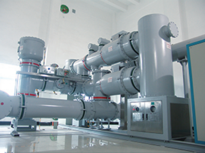
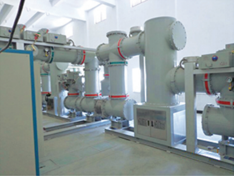
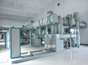
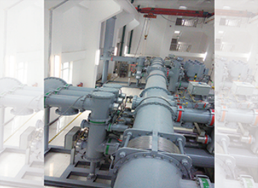
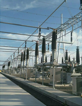
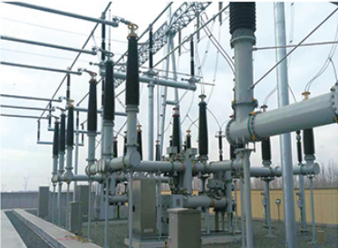
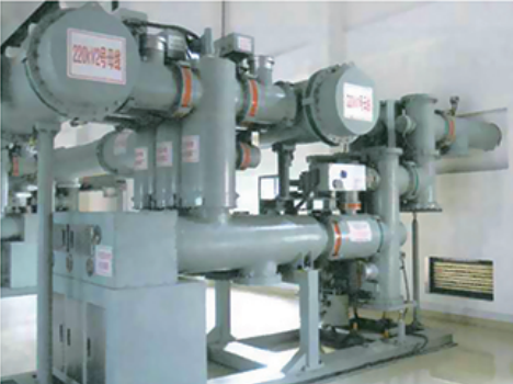
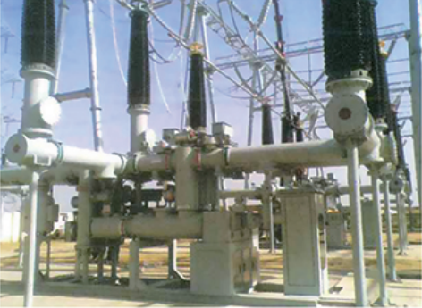
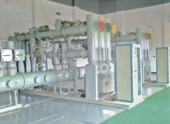
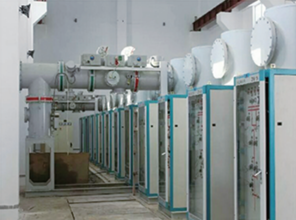
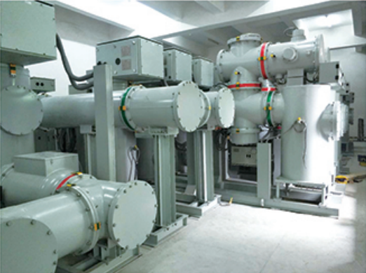
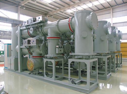
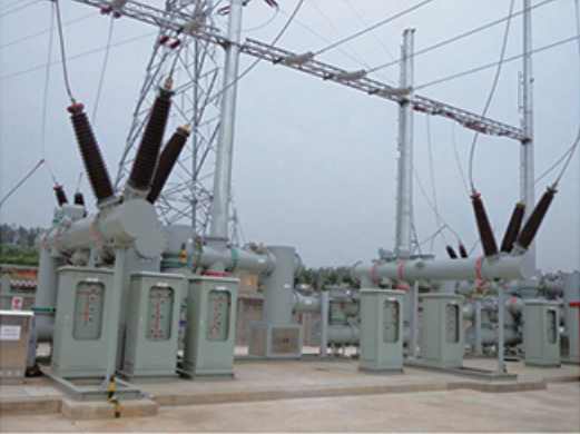
220kV SF6 Gas-Insulated Gapless Metal Oxide Surge Arrester for AC Systems: 

The 220 kV SF6 Gas-Insulated Gapless Metal Oxide Surge Arrester offers exceptional surge protection for AC systems, combining advanced gapless MOV technology and SF6 gas insulation for superior reliability and performance. Perfect for substations and critical power infrastructure. Contact us for pricing and customization.

Trusted by world-class brands & organizations of all sizes

Product Feature

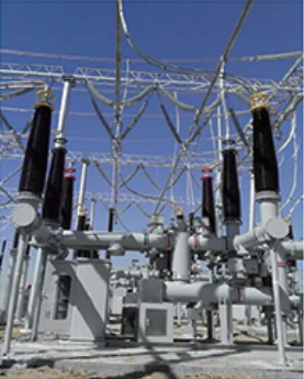
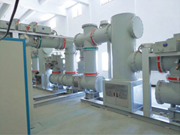
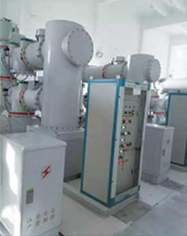
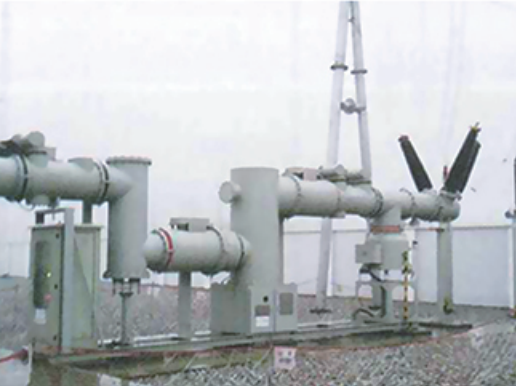
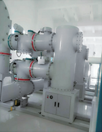
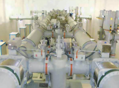
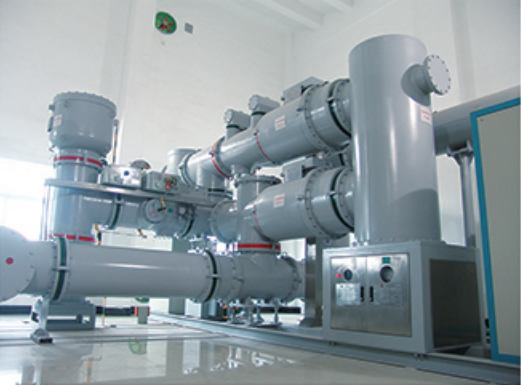
The 220 kV SF6 Gas-Insulated Gapless Metal Oxide Surge Arrester is engineered to provide high-performance surge protection for critical high-voltage AC systems. Designed to protect against overvoltages caused by lightning strikes or switching operations, this arrester features a gapless metal oxide varistor (MOV) design, which ensures excellent surge absorption and minimal residual voltage. The gapless construction allows the arrester to handle high-energy transients without the risk of spark gap degradation, providing reliable and consistent protection.

The SF6 gas insulation enhances the dielectric strength of the arrester, enabling it to withstand significant surge currents and high voltages while maintaining a compact and robust form factor. This design ensures long operational life, low maintenance needs, and superior performance in harsh environmental conditions, making it an ideal solution for substations and power transmission systems.

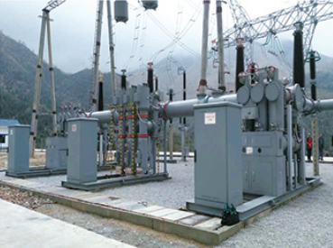
Applications for the 220 kV SF6 Gas-Insulated Surge Arrester include power grids, industrial plants, and renewable energy installations where high-voltage surge protection is crucial. The arrester’s gapless design and SF6 insulation provide reliable, maintenance-free performance, ensuring the safety and stability of electrical infrastructure. Contact us for customized solutions to meet your specific requirements.

Technical Parameters

220kV SF6 MOV Arrester Technical Parameters
No.Parameter NameUnitParameter (110kV)Parameter (220kV)
1System Nominal VoltagekV110220
2System Maximum VoltagekV126252
3System Rated VoltagekV102204
4Lightning Arrester Continuous Operating VoltagekV79.6159
5Nominal Discharge Current (8/20μs)kA1010
6Residual Voltage under Steep Front Impulse Current (1/100μs)kV≤297≤594
7Residual Voltage under Lightning Impulse Current (8/20μs)kV≤266≤532
8Residual Voltage under Operation Impulse Current (30/60μs)kV≤226≤452
9DC 1mA Reference Voltage (Peak)kV≥102≥296
10Leakage Current at 75% of DC 1mA Reference VoltageμA5050
11Power Frequency Reference VoltagekV≥102≥204
12Partial Discharge AmountpC≤10≤10
13Continuous CurrentμA≤200≤350
14Long Duration Impulse Withstand Current (Line Discharge Class) 600800
 Long Duration Impulse Withstand Current (Square Wave Current Impulse)A600800
154/10μs Large Impulse Withstand Current (Two Times)kA100100

FAQs

Gas Insulated Switchgear (GIS) FAQs

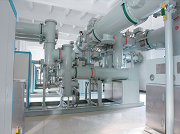
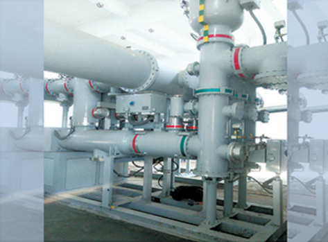
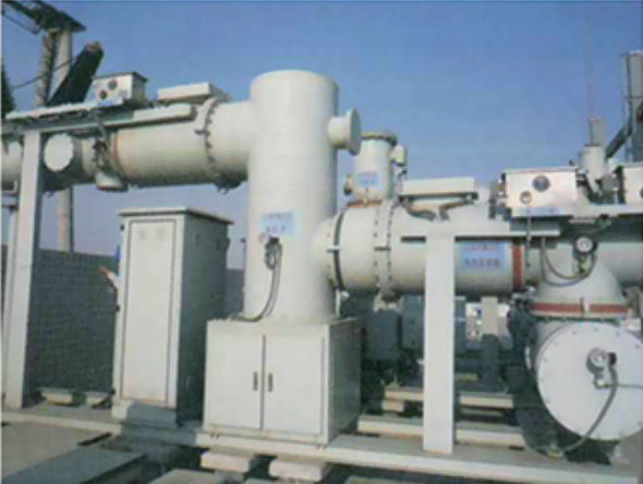
When purchasing a Gas Insulated Switchgear (GIS), you may want to know the following questions & answers.

The rated voltage and current capacity of Gas Insulated Switchgear (GIS) depend on the specific design, manufacturer, and application for which the GIS is intended. However, I can provide you with a general overview of typical specifications for GIS systems in common industrial and utility applications.

1. Rated Voltage:

GIS systems are designed for high-voltage applications, typically ranging from:

  • Medium Voltage GIS:

    • Voltage Range: 12 kV to 36 kV
    • Common applications: Distribution networks, industrial installations.
  • High Voltage GIS:

    • Voltage Range: 72.5 kV to 800 kV
    • Common applications: Transmission systems, substations.
  • Ultra High Voltage GIS:

    • Voltage Range: 1,000 kV and above
    • Common applications: Large transmission grids, interconnecting countries or regions.

2. Rated Current Capacity:

The rated current capacity of a GIS is primarily dependent on the system’s design and its intended application. Some general values are:

  • Rated Current:
    • For medium-voltage GIS: It typically ranges from 630 A to 4,000 A.
    • For high-voltage GIS: It typically ranges from 1,000 A to 4,000 A.

However, GIS systems can be designed for even higher currents depending on the requirements. For example:

  • Rated Current for extra-high voltage GIS: Can range from 4,000 A to 6,000 A or higher, based on the specific application (such as large substations or long-distance transmission lines).

3. Key Design Considerations Affecting Voltage and Current Ratings:

  • Gas Type: GIS typically uses SF6 (Sulfur Hexafluoride) as the insulating gas, which allows for compact designs with higher voltage ratings and current carrying capacity.
  • Switching Capacity: GIS designs also factor in the rated short-circuit breaking capacity, which defines how much fault current the switchgear can interrupt.
  • Arc-Extinguishing Technology: The GIS is equipped with circuit breakers that can interrupt fault currents without causing arc flash damage to the system.

In Summary:

  • Rated Voltage: From 12 kV to 800 kV (and higher in specialized systems).
  • Rated Current: From 630 A to 6,000 A (or higher).

These values can vary based on the design and application. Would you like to know about specific GIS models or manufacturers for more detailed specifications?

The design life expectancy of Gas Insulated Switchgear (GIS) is typically in the range of 30 to 40 years. This is a general benchmark, but the actual lifespan can vary depending on several factors, such as:

1. Environmental Conditions

  • Indoor vs. Outdoor GIS: GIS systems are often installed in controlled indoor environments (like substations), which can extend their life expectancy compared to outdoor installations exposed to harsh weather conditions.
  • Ambient Temperature and Humidity: Extremely high or low temperatures, as well as high humidity, can affect the insulation and mechanical components.
  • Pollution Levels: High pollution environments may lead to faster degradation of certain components.

2. Maintenance Practices

  • GIS systems are designed for low-maintenance operation, but periodic maintenance and inspections are required to ensure optimal performance and longevity.
  • Regular insulation checks (for SF6 gas leakage and pressure) and monitoring of mechanical components (like circuit breakers and switches) can help prevent early failures.
  • Gas quality: SF6 gas quality is crucial; if gas leaks or moisture enters, it can impact performance and reduce life expectancy. Regular gas pressure checks and refilling can extend the lifespan of the system.

3. Technological Advancements and Upgrades

  • Over time, GIS technology may undergo improvements in materials or construction, potentially influencing lifespan. Newer models may feature enhanced insulation, more robust materials, and advanced monitoring systems, contributing to longer operational life.

4. Quality of Components and Manufacturing

  • Manufacturer-specific designs and the quality of materials used in construction (e.g., SF6 purity, insulation materials, metal parts) can impact both the reliability and longevity of the GIS.
  • Design specifications from reputable manufacturers tend to support a longer life expectancy, with careful engineering of components for longevity and ease of maintenance.

5. Operating Conditions and Stress

  • High electrical stress (such as frequent switching, high fault currents, or other operational stresses) can contribute to degradation, reducing the GIS’s service life.
  • Well-maintained GIS systems operating within their design parameters tend to last closer to the 40-year range.

6. Replacement and Upgrade Options

  • After the initial service life, GIS systems may still function but may require significant maintenance, upgrades, or even replacement of some components, such as circuit breakers, insulation, or gas chambers.
  • Manufacturers and utilities sometimes opt for refurbishment or retrofit solutions to extend the life of GIS beyond the typical 30–40 years.

Conclusion:

While the typical design life expectancy of GIS is 30 to 40 years, the actual life span can be influenced by factors like maintenance, operational stress, environmental conditions, and technological upgrades. Proper monitoring and care can ensure that a GIS remains functional and safe beyond its initial design life.

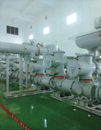
Yes, Gas Insulated Switchgear (GIS) can be highly customized to meet specific operational requirements, and this is one of its key advantages. GIS is designed to be flexible and adaptable, offering various configurations, ratings, and features to suit different environments, applications, and operational needs. Here’s how GIS can be customized:

1. Voltage and Current Ratings

  • Rated Voltage: GIS can be tailored to different voltage levels, ranging from 12 kV (for medium voltage applications) to 1,200 kV or more (for ultra-high voltage transmission systems). Manufacturers can adjust the voltage rating according to the requirements of the electrical grid or industrial system.
  • Rated Current: Custom current capacities (e.g., 630 A, 1,200 A, 4,000 A, etc.) can be selected based on the needs of the installation, whether for light industrial or high-capacity transmission applications.
  • Short-Circuit Withstand Capacity: GIS systems can be designed with specific short-circuit breaking capacities to handle the expected fault currents of a particular grid or system.

2. Switching and Protection Functions

  • Circuit Breakers and Disconnectors: GIS can include various types of circuit breakers, such as vacuum or SF6 circuit breakers, and can integrate specific disconnector and earthing switch configurations based on the switching and protection needs of the network.
  • Fault Detection and Monitoring: Customized GIS designs can incorporate advanced monitoring and protection systems, such as current transformers (CTs), voltage transformers (VTs), gas density monitoring, and temperature sensors, to provide real-time diagnostics and early fault detection.

3. Gas Insulation and Pressure Management

  • SF6 Gas Handling: The GIS can be customized to include different gas handling systems based on the expected operational conditions, including SF6 gas leakage monitoring, gas filling and refilling systems, and gas density sensors.
  • Environmental Considerations: For projects in areas with extreme climates (e.g., high temperatures or low temperatures), GIS can be modified to ensure proper gas pressure management or cooling systems to maintain optimal performance.
  • Alternative Gas Solutions: Some manufacturers are exploring alternatives to SF6, like fluoronitrile-based gases (e.g., 3M’s Novec), which are more environmentally friendly. Custom GIS units can be designed to use these alternative gases if required by the specific environmental or regulatory needs.

4. Compactness and Space-Saving Designs

  • Modular and Scalable Systems: GIS can be built with modular designs that allow for easy scalability. These designs allow customers to choose the number of compartments (e.g., circuit breakers, disconnectors) and customize their GIS system layout based on space constraints or expansion requirements.
  • Space-Saving: GIS is ideal for installations where space is limited, and it can be customized to be even more compact based on installation requirements, such as in urban substations or underground installations.

5. Busbar Configuration and Layout

  • The busbar configuration in GIS can be customized according to the layout of the electrical network or substation. This includes choices for single bus, double bus, or ring bus systems depending on reliability, flexibility, and operational requirements.
  • Dual Busbar Systems: In critical infrastructure, such as power generation stations or large substations, GIS can be designed with dual busbar systems for redundancy and increased reliability.

6. Control and Automation Features

  • SCADA Integration: GIS can be customized with advanced control systems that allow for integration with Supervisory Control and Data Acquisition (SCADA) systems for remote monitoring, control, and automation.
  • Smart GIS: Advanced digital sensors and communication interfaces can be incorporated into GIS to enable real-time condition monitoring, predictive maintenance, and fault isolation, providing enhanced automation and decision-making capabilities.

7. Seismic and Environmental Customization

  • Seismic Resistance: For installations in earthquake-prone areas, GIS can be customized to meet seismic standards and ensure that the equipment remains operational during and after a seismic event.
  • Corrosion Resistance: In environments with high humidity, salt, or other corrosive elements (e.g., coastal regions), GIS can be customized with corrosion-resistant coatings or specially designed materials to ensure durability.

8. Specific Application Customization

  • Utility and Transmission Systems: GIS can be customized for high-voltage applications like interconnecting grids, inter-region power transmission, or offshore platforms with enhanced capabilities for high-voltage operations and fault handling.
  • Industrial Applications: For large factories or data centers, GIS can be tailored for medium-voltage requirements with custom protection and control options, as well as features for maintenance-free operation and minimal downtime.

9. Safety and Environmental Concerns

  • Leak Detection and Alarm Systems: Custom safety features such as SF6 gas leak detectors, alarms, and automatic isolation systems can be integrated to prevent environmental hazards.
  • Zero Gas Emission Options: There is growing demand for environmentally friendly GIS options. Some manufacturers offer SF6-free GIS solutions or designs that use alternative insulating gases (such as clean air or eco-friendly SF6 alternatives).

Conclusion

In summary, GIS systems are highly customizable to meet a wide range of operational, environmental, and regulatory needs. From voltage and current ratings to advanced protection, automation, and gas handling systems, GIS can be specifically designed to suit the unique requirements of industrial, utility, and transmission applications. Customizing GIS is a common practice for ensuring that the switchgear performs optimally in specific use cases while meeting safety, efficiency, and space requirements. If you have a specific operational need, the customization options for GIS are flexible enough to adapt.

Gas Insulated Switchgear (GIS) typically uses insulating gases to provide high dielectric strength and prevent electrical arcing in the switchgear. The most commonly used gases in GIS are SF6 (Sulfur Hexafluoride) and alternative gases that are more environmentally friendly. Let’s go over the different types of gases used in GIS and the environmental considerations for each:

1. SF6 (Sulfur Hexafluoride)

  • Usage: SF6 is the most widely used gas in GIS due to its superior dielectric properties and arc-quenching capabilities. It provides excellent insulation and is effective in preventing electrical breakdowns in high-voltage systems.

  • Environmental Considerations:

    • Global Warming Potential (GWP): SF6 has an extremely high GWP, around 23,500 times greater than CO₂ over a 100-year period. This makes it a potent greenhouse gas if it leaks into the atmosphere.
    • Leakage: SF6 is a colorless, odorless gas and leaks are difficult to detect without specific equipment. Even small leaks over time can have a significant environmental impact.
    • Regulations and Alternatives: Due to its high GWP, SF6 is under increasing regulatory scrutiny. Organizations are actively working to minimize SF6 use or to find alternatives. The EU F-Gas Regulation and other global standards are encouraging the reduction of SF6 emissions.
    • Recovery and Recycling: Modern GIS designs often include systems for the recovery and recycling of SF6 gas to prevent environmental impact. This helps ensure that any SF6 released during maintenance or at the end of the GIS’s life can be captured and reused.

2. Air (Clean Air or Dry Air)

  • Usage: Air-insulated switchgear (AIS) typically uses ambient air as the insulation medium. However, for GIS, clean air or dry air is increasingly being used as an alternative to SF6. This is especially true for systems where a reduced environmental impact is a priority.

  • Environmental Considerations:

    • Zero Global Warming Potential (GWP): Clean air has no GWP and does not contribute to global warming or ozone depletion, making it an environmentally friendly alternative.
    • Non-toxic and Non-flammable: Clean air is naturally non-toxic and non-flammable, making it safer for human health and less risky in the event of a gas leak.
    • Operational Challenges: Clean air can be less effective than SF6 for insulating in high-voltage applications, requiring larger and more robust equipment to achieve the same level of performance. It also requires precise moisture control, as high humidity can degrade its dielectric properties.
  • Availability: Clean air is abundant, inexpensive, and easy to manage, making it a sustainable alternative. However, it is still relatively new in large-scale GIS applications, and its use is primarily seen in lower-voltage systems (up to 72.5 kV).

3. Fluoronitrile-Based Gases

  • Usage: Gases like C6HFN (fluoronitrile), which is a type of fluoronitrile-based gas, have emerged as potential alternatives to SF6. They are typically used in combination with other gases such as CO₂ to achieve the desired dielectric strength for GIS systems.

  • Environmental Considerations:

    • Lower Global Warming Potential (GWP): Fluoronitrile-based gases have a much lower GWP than SF6, typically less than 1,000 times that of CO₂, making them far more environmentally sustainable.
    • Biodegradability: Fluoronitrile gases are considered to be more biodegradable than SF6, meaning they break down more easily in the environment, reducing long-term environmental impact in the event of leakage.
    • Non-toxic and Safe: These gases are designed to be non-toxic, ensuring that they pose minimal risk to human health, provided the GIS system is properly maintained.
  • Availability: Fluoronitrile-based gases are still relatively new in the market, and while they show promise, their use is not yet as widespread as SF6. Companies like 3M and General Electric are leading efforts to incorporate these gases into GIS and other high-voltage equipment.

4. CO₂ (Carbon Dioxide)

  • Usage: CO₂ is sometimes used in hybrid GIS designs, often mixed with other gases, such as fluoronitriles or clean air, to provide adequate insulation and arc-quenching capabilities.

  • Environmental Considerations:

    • Zero Ozone Depletion Potential (ODP): CO₂ has no ODP and is naturally abundant in the environment, meaning it does not contribute to ozone layer depletion.
    • Global Warming Potential (GWP): CO₂ has a GWP of 1, which is significantly lower than SF6, but still a greenhouse gas. The environmental impact of CO₂ is mainly dependent on the amount used in the GIS system.
    • Safety and Toxicity: CO₂ is non-toxic in typical GIS concentrations, but asphyxiation can be a concern in confined spaces if the gas concentration is too high. Special precautions should be taken in enclosed environments.

5. Alternative Gases (Other Fluorinated Gases)

  • Other gases such as gaseous mixtures or fluorinated esters are being researched and trialed as potential alternatives to SF6 in GIS. These gases may offer a balance between effective insulation, low GWP, and compatibility with existing GIS technology.

  • Environmental Considerations:

    • The GWP of these gases varies depending on the specific compound used, but many offer significant environmental advantages over SF6, especially when blended with CO₂ or other gases.
    • These gases tend to be more environmentally friendly but may have limited commercial availability or face technical challenges in terms of dielectric strength and long-term stability.

Environmental Summary:

  • SF6: Highly effective for GIS insulation but has a very high global warming potential (GWP). Regulatory pressure is increasing to reduce its use and replace it with lower-GWP alternatives.

  • Clean Air: Zero GWP, environmentally friendly, and non-toxic, but requires large-scale infrastructure and precise moisture control. Primarily used in medium-voltage GIS.

  • Fluoronitrile-Based Gases: Lower GWP, biodegradable, and non-toxic, making them a promising alternative to SF6. Their use is still growing and typically suited for high-voltage GIS.

  • CO₂: Zero ODP and low GWP, but typically used in hybrid systems with other gases. Safe in typical concentrations but needs careful management.

  • Other Fluorinated Gases: Gases like fluorinated esters or mixtures with CO₂ are under development as low-impact alternatives, and offer promising environmental benefits.

Conclusion:

The trend in GIS design is moving toward environmentally friendlier insulating gases, primarily to reduce the environmental impact of SF6. Alternatives like clean air, fluoronitrile-based gases, and CO₂ mixtures offer reduced GWP and better sustainability profiles. However, there are still challenges in achieving the same level of dielectric strength and performance as SF6, which is why SF6 is still the most widely used gas in GIS, though alternatives are gaining traction with advancing technology and regulations.

The short-circuit withstand strength of Gas Insulated Switchgear (GIS) refers to the ability of the switchgear to withstand and interrupt the fault current during a short-circuit event without being damaged. This is a critical characteristic in ensuring the reliability and safety of the power system, as GIS systems are often deployed in high-voltage transmission and distribution networks where fault conditions can occur.

Short-Circuit Withstand Strength of GIS:

  1. Rated Short-Circuit Withstand Strength:

    • The short-circuit withstand strength of a GIS is typically measured in terms of its rated short-circuit current, which is the maximum current the GIS can withstand for a specified period without structural or operational failure.
    • Short-circuit withstand ratings are usually expressed as the maximum short-circuit current (Icc) and the duration of the fault that the switchgear can handle, commonly in kA (kiloamperes) and milliseconds (ms).
    • The short-circuit withstand time is usually around 1 second or 3 seconds, depending on the design and the required performance standard.
  2. Typical Ratings:

    • Medium Voltage GIS (12 kV to 36 kV): The short-circuit withstand strength is typically in the range of 16 kA to 40 kA (for 1 second), depending on the specific application.
    • High Voltage GIS (72.5 kV to 800 kV): These systems usually have a short-circuit withstand strength in the range of 40 kA to 63 kA (for 1 second), or even higher for specialized applications.
    • Extra High Voltage GIS (>800 kV): For ultra-high voltage GIS systems, the short-circuit withstand strength can go up to 80 kA or higher for a 1-second duration, depending on the design and operational requirements.
  3. Break Time:

    • Interruption Time: GIS systems are designed to interrupt fault currents as quickly as possible, typically in < 5 cycles (100–150 milliseconds) for high-voltage GIS.
    • The circuit breakers within the GIS, which are responsible for interrupting fault currents, are usually capable of making and breaking high fault currents within fractions of a second.

Compliance with International Standards:

GIS systems are designed and tested to comply with various international standards related to electrical safety, performance, and environmental impact. Some key standards that address short-circuit withstand strength and related parameters include:

  1. IEC Standards (International Electrotechnical Commission):
    • IEC 62271-100: This is the most widely accepted standard for high-voltage switchgear and controlgear, including GIS. It specifies the requirements for the short-circuit withstand strength of switchgear, including the testing methods and the rated short-circuit breaking current (Isc) and withstand current (Icw).
    • According to this standard, GIS must be able to withstand short-circuit currents for a specified duration (usually 1 second) and should be capable of safely interrupting the fault current when the circuit breaker operates.
  2. IEEE Standards (Institute of Electrical and Electronics Engineers):
    • IEEE C37.04: This standard provides guidelines for the ratings and testing of high-voltage circuit breakers, including GIS circuit breakers.
    • It sets requirements for short-circuit withstand strength, with particular emphasis on the current and the duration the equipment can endure during fault conditions.
  3. ANSI Standards:
    • ANSI C37.04: This standard, applicable primarily in North America, also covers short-circuit withstand and interruption capabilities for GIS systems, including the handling of fault currents and the maximum interrupting ratings.
  4. ISO Standards:
    • ISO 9001 and ISO 14001: Although not directly related to short-circuit withstand strength, these standards are critical in ensuring the quality management and environmental management of the manufacturing processes for GIS, ensuring that the systems meet high safety and performance standards.
  5. IEC 62271-200: For metal-enclosed switchgear, including GIS, this standard also provides guidance on the design, testing, and short-circuit withstand capacity of equipment under various fault conditions.

Testing and Validation:

To ensure compliance with these international standards, GIS manufacturers perform several rigorous tests to validate the short-circuit withstand strength:

  • Short-Circuit Withstand Test (Icw): The GIS is subjected to a fault current for the specified duration (usually 1 second) to ensure that it can endure without failure.
  • Short-Circuit Making Test (Icm): This test evaluates the ability of the GIS to close the switch under fault conditions (making the circuit during a short-circuit event).
  • Break Time Test: Ensures that the GIS can interrupt the fault current within the required time.

Conclusion:

  • Short-circuit withstand strength of GIS is typically in the range of 16 kA to 80 kA (or higher) depending on the voltage level and the application.
  • The GIS is designed to meet international standards such as IEC 62271-100, IEEE C37.04, and ANSI C37.04, which ensure its reliability and safety during short-circuit conditions.
  • These standards govern the maximum fault currents that GIS can withstand and interrupt, ensuring that the switchgear performs effectively without structural damage or compromising safety.

The IP (Ingress Protection) rating of Gas Insulated Switchgear (GIS) is a measure of its ability to protect against the ingress of solid objects (like dust) and liquids (such as water). The IP rating system is defined by the IEC 60529 standard, which assigns a two-digit code to indicate the level of protection.

Understanding the IP Rating System:

  1. First Digit (Solid Object Protection): The first digit indicates the level of protection against the ingress of solid objects, such as dust, debris, or fingers.

    • 0: No protection.
    • 1: Protection against objects larger than 50 mm (e.g., a hand).
    • 2: Protection against objects larger than 12 mm (e.g., a finger).
    • 3: Protection against objects larger than 2.5 mm (e.g., a tool or wire).
    • 4: Protection against objects larger than 1 mm (e.g., small tools or wires).
    • 5: Dust-protected; limited ingress of dust is allowed, but it will not interfere with the equipment’s operation.
    • 6: Dust-tight; no ingress of dust.
  2. Second Digit (Liquid Protection): The second digit represents the protection against the ingress of liquids, such as water.

    • 0: No protection.
    • 1: Protection against vertically falling water drops.
    • 2: Protection against water drops falling at up to a 15° angle.
    • 3: Protection against water sprays at an angle of up to 60°.
    • 4: Protection against water splashes from any direction.
    • 5: Protection against water jets from any direction.
    • 6: Protection against heavy seas or powerful water jets.
    • 7: Protection against immersion in water up to 1 meter for 30 minutes.
    • 8: Protection against immersion in water beyond 1 meter depth.

IP Rating of GIS:

For Gas Insulated Switchgear (GIS), the typical IP rating is IP67 or IP68.

  • IP67: This rating indicates the following:

    • 6: Dust-tight; no dust can enter the GIS enclosure.
    • 7: Protected against immersion in water up to 1 meter depth for 30 minutes. This means the GIS is sealed enough to prevent the ingress of water even when submerged in shallow water.
  • IP68: Some GIS systems designed for more challenging environmental conditions may have an IP68 rating:

    • 6: Dust-tight; complete protection against dust ingress.
    • 8: Protected against long-term immersion in water beyond 1 meter depth (often specified by the manufacturer, e.g., up to 3 meters or more).

Why IP Rating is Important for GIS:

  • Environmental Protection: GIS are often used in environments where exposure to dust, water, and other contaminants is a concern. The IP rating ensures that the GIS is hermetically sealed, providing long-term protection from environmental factors that could otherwise degrade performance or cause system failure.
  • Maintenance-Free: The sealed nature of GIS allows it to operate maintenance-free for extended periods (often 20-40 years), as the insulation is protected from external contaminants that could interfere with its function.
  • Urban and Outdoor Installations: GIS with high IP ratings (like IP67 or IP68) are ideal for urban substations or outdoor installations where protection from harsh weather conditions, dust, rain, and flooding is necessary.

Summary:

  • The typical IP rating of GIS is IP67 or IP68, which provides excellent protection against dust and water ingress, ensuring that the GIS can function effectively even in challenging environmental conditions.
  • This high degree of protection makes GIS suitable for a wide range of applications, including urban, industrial, and outdoor settings where environmental conditions could compromise other types of switchgear.

QC & Guarantee

Market Orientation and Service Commitment

In response to fierce market competition and to meet customer demands, our company adheres to a market-oriented approach and a customer-centric philosophy. We have earned widespread recognition from our clients through efficient, comprehensive services and superior product quality.

Our Commitments

  1. Product Lifespan Guarantee: The operational lifespan of our transformers is no less than 30 years.
  2. Strict Quality Control:
    • Upon receiving bid documents, we promptly initiate the evaluation process to ensure all customer requirements are fully addressed.
    • We carefully select certified suppliers and strictly follow quality management standards to control and inspect raw materials and components.
    • We produce high-quality, customer-satisfactory parts in full compliance with contract and technical agreement requirements.
  3. After-Sales Service Commitment:
    • All performance indicators and technical specifications of our transformers meet or exceed national standards.
    • Within 3 years of installation and commissioning, if any oil leakage occurs due to manufacturing defects in oil-immersed transformers, we will repair it at no cost.
    • For any critical component defects identified during production or issues discovered during installation, we prioritize resolution to meet project timelines, followed by thorough responsibility analysis and necessary repairs or replacements.
    • We welcome customers to supervise the manufacturing process at our facility and will provide full support.

After-Sales Support

We offer comprehensive after-sales services, including free guidance for installation and commissioning. After the product is operational, if the customer requires support, our service team will respond promptly:

  • Arrival on-site within 24 hours for locations within 300 km.
  • Arrival on-site within 48 hours for locations beyond 300 km.

Additionally, we have established a robust regular follow-up system. We conduct periodic written or on-site visits to monitor the performance of in-service products, ensuring our customers have continuous peace of mind.

International Service Methods

Remote Technical Assistance

Our service team provides 24/7 online technical support, including video calls, troubleshooting guides, and documentation, ensuring immediate assistance regardless of time zones.
Detailed remote diagnostics can be conducted using customer-provided data or live visual inspections.

On-Site Support

For complex issues, we dispatch experienced technicians to the customer site promptly, adhering to the agreed international response timelines.
On-site services include installation guidance, commissioning, maintenance, and repairs.

Dedicated Service Representatives

Each international client is assigned a dedicated service representative to coordinate all aspects of after-sales support, including issue resolution and regular follow-ups.

Local Service Partnerships

We collaborate with certified local service partners in key markets to ensure faster response times and efficient support. These partners are fully trained in our products and processes to uphold our quality standards.
Regular Follow-Up Visits

Post-installation, we perform scheduled follow-up visits, either in person or virtually, to monitor product performance and address customer feedback. This proactive approach ensures optimal operation and customer satisfaction.

Why This Matters

Our comprehensive international service system combines swift response, advanced technical support, and localized expertise to provide our global clients with reliable and professional after-sales services. We are committed to building lasting partnerships through consistent support and excellence.

Ultimate Guide

Gas Insulated Switchgear (GIS) Ultimate Guide

Faster global delivery

lifespan > 30 years

Top10 Power equipment cop in CN
National-level technology center

Why Choose us ?

Built to last,
engineered to perform.

Taishan Transformer is a key national-level manufacturer specializing in transformers, recognized as a “Contract-Honoring and Promise-Keeping” enterprise, a high-tech enterprise, and a national-level enterprise technology center. It is recommended in the national directory for rural and urban power grid construction and renovation, as well as a recommended supplier of major electromechanical equipment for hydropower projects. Its products have been awarded the title of “National Quality Inspection Qualified Product – Quality Trustworthy Product” and “Nationally Recognized Product for Mechanical Industry Users.

Get a Quote / Support for Your Project

  • Don’t worry, we hate spam too!