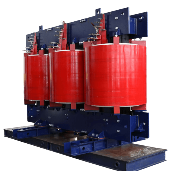
35kV and below resin casting dry-type transformer of our company with high insulation strength, strong short-circuit resistance, and environmental protection, fire protection, explosion protection, maintenance-free and other advantages, is welcomed by the vast numbers of users. At present, the capacity of natural cooling resin casting dry-type transformer can reach 25000kVA for one set, voltage level covers 10kV~35kV, nearly 100 specifications and models.

Trusted by world-class brands & organizations of all sizes
| Specification | Po (W) | Pk (w) (75°C ) | Uk (%) | lo (%) | LpA (dB) | Wt (kg) | Dimensions(mm) | LV Terminal |
|||
|---|---|---|---|---|---|---|---|---|---|---|---|
| a | b | c | d | ||||||||
| SC12-800/35 | 1800 | 8260 | 6 | 0.7 | 58 | 3500 | 2010 | 1600 | 1814 | 820 | |
| SC12-1000/35 | 2140 | 9570 | 0.6 | 58 | 4400 | 2020 | 1600 | 1960 | 820 | ||
| SC12-1250/35 | 2500 | 11330 | 0.6 | 58 | 4900 | 2250 | 1600 | 2040 | 820 | ||
| SC12-1600/35 | 2950 | 13520 | 0.6 | 58 | 5600 | 1945 | 1600 | 2218 | 1070 | ||
| SC12-2000/35 | 3380 | 15980 | 7 | 0.5 | 60 | 8000 | 2310 | 1600 | 2090 | 1070 | |
| SC12-2500/35 | 3890 | 19140 | 0.5 | 60 | 8700 | 2310 | 1600 | 2390 | 1070 | ||
| SC12-3150/35 | 4820 | 21510 | 8 | 0.4 | 60 | 8900 | 2430 | 1600 | 2428 | 1070 | |
| SC12-4000/35 | 5620 | 25810 | 0.4 | 62 | 11370 | 2200 | 1400 | 2024 | 1780 | ||
| SC12-5000/35 | 6690 | 30640 | 0.4 | 63 | 12940 | 2700 | 1330 | 2720 | 1780 | ||
| SC12-6300/35 | 7920 | 35820 | 0.3 | 63 | 16000 | 3120 | 1330 | 2850 | 1780 | ||
| SC12-8000/35 | 9040 | 40380 | 9 | 0.3 | 63 | 18000 | 3160 | 1600 | 2860 | 1780 | |
| SC12-10000/35 | 10300 | 48720 | 0.3 | 63 | 20500 | 3120 | 2160 | 2920 | 1800 | ||
| SC12-12500/35 | 12600 | 56700 | 0.2 | 68 | 24300 | 3390 | 2160 | 2950 | 1800 | ||
| SC12-16000/35 | 15400 | 66710 | 0.2 | 68 | 39000 | 4500 | 2160 | 2970 | 1800 | ||
| SC12-20000/35 | 18300 | 75050 | 0.2 | 70 | 42000 | 3980 | 2660 | 3290 | 1800 | ||
| SC12-25000/35 | 21700 | 88650 | 10 | 0.2 | 73 | 53000 | 4450 | 2660 | 3490 | 1800 | |
| Note: | |||||||||||
| 1.The overal dimensions listed above are for design and type selection only. The final size shall be taken as per the product drawing. | |||||||||||
| 2. Capacity of 4000kVA and above products is usualy not equipped with enclosures, if necessary, can be configured guardrail. | |||||||||||
| Specification | Po (W) | Pk(W) (75%) | Uk (%) | lo (%) | LpA (dB) | Wt (kg) | Dimensions (mm) | LV Terminal |
||||||
|---|---|---|---|---|---|---|---|---|---|---|---|---|---|---|
| a | b | c | d | e | f | g | ||||||||
| SC12-630/10 | 1150 | 5590 | 6 | 0.8 | 60 | 2530 | 1660 | 1200 | 1600 | 820 | 2000 | 1400 | 2200 | |
| SC12-800/10 | 1300 | 6680 | 0.8 | 61 | 3060 | 1680 | 1200 | 1759 | 820 | 2000 | 1400 | 2200 | ||
| SC12-1000/10 | 1550 | 7710 | 0.8 | 61 | 3640 | 1750 | 1200 | 1880 | 820 | 2000 | 1400 | 2200 | ||
| SC12-1250/10 | 1870 | 9130 | 0.8 | 62 | 4190 | 1890 | 1200 | 1980 | 820 | 2300 | 1400 | 2200 | ||
| SC12-1600/10 | 2230 | 11150 | 0.6 | 62 | 4780 | 2050 | 1400 | 1940 | 820 | 2500 | 1600 | 2400 | ||
| SC12-2000/10 | 2880 | 13350 | 0.5 | 63 | 5670 | 2070 | 1400 | 2170 | 1070 | 2500 | 1600 | 2400 | ||
| SC12-2500/10 | 3380 | 15630 | 0.5 | 63 | 6800 | 2200 | 1400 | 2069 | 1070 | 2500 | 1600 | 2400 | ||
| SC12-3150/10 | 4030 | 18350 | 7 | 0.5 | 64 | 8050 | 2300 | 1400 | 2320 | 1070 | 2500 | 1600 | 2800 | |
| SC12-4000/10 | 4820 | 22040 | 0.4 | 65 | 9450 | 2450 | 1400 | 2415 | 1070 | 2800 | 1600 | 2800 | ||
| SC12-5000/10 | 5760 | 26070 | 0.4 | 65 | 11450 | 2700 | 1600 | 2445 | 1475 | 3000 | 2000 | 2800 | ||
| SC12-6300/10 | 6800 | 30990 | 0.4 | 66 | 13450 | 2900 | 1600 | 2545 | 1475 | 3300 | 2000 | 2900 | ||
| SC12-8000/10 | 8300 | 37710 | 8 | 0.3 | 66 | 15300 | 3000 | 1600 | 2650 | 1475 | 3500 | 2000 | 3000 | |
| SC12-10000/10 | 9720 | 42520 | 0.3 | 66 | 20000 | 3250 | 1600 | 2730 | 1475 | 3600 | 2000 | 3200 | ||
| Note: | ||||||||||||||
| The dimensions listed in the above table are only for the reference of design and selection, and the final dimensions are subject ot the product outline drawings. | ||||||||||||||
| Specification | Po (W) | Pk(w) (120°C) | Uk (%) | lo (%) | LpA (dB) | Wt (kg) | Dimensions(mm) | LV Terminal |
||||||
|---|---|---|---|---|---|---|---|---|---|---|---|---|---|---|
| a | b | c | d | e | f | g | ||||||||
| SC18-30/10 | 105 | 640 | 4 | 1.6 | 48 | 510 | 785 | 800 | 860 | 400 | 1200 | 1100 | 1600 | |
| SC18-50/10 | 155 | 900 | 1.6 | 48 | 620 | 855 | 800 | 910 | 400 | 1200 | 1100 | 1600 | ||
| SC18-80/10 | 210 | 1240 | 1.4 | 48 | 740 | 1020 | 800 | 1104 | 400 | 1400 | 1100 | 1800 | ||
| SC18-100/10 | 230 | 1415 | 1.4 | 48 | 840 | 1020 | 800 | 1104 | 400 | 1400 | 1100 | 1800 | ||
| SC18-125/10 | 270 | 1665 | 1 | 48 | 940 | 1050 | 800 | 1104 | 400 | 1500 | 1100 | 1800 | ||
| SC18-160/10 | 310 | 1915 | 1 | 48 | 1250 | 1150 | 800 | 1159 | 550 | 1700 | 1300 | 1800 | ||
| SC18-200/10 | 360 | 2275 | 1 | 50 | 1300 | 1150 | 1000 | 1169 | 550 | 1700 | 1300 | 1800 | ||
| SCB18-250/10 | 415 | 2485 | 1 | 50 | 1750 | 1150 | 1000 | 1199 | 550 | 1700 | 1300 | 1800 | ||
| SCB18-315/10 | 510 | 3125 | 0.8 | 50 | 1800 | 1180 | 1000 | 1120 | 660 | 1700 | 1300 | 1800 | ||
| SCB18-400/10 | 570 | 3590 | 0.8 | 51 | 2200 | 1180 | 1000 | 1210 | 660 | 1700 | 1300 | 1800 | ||
| SCB18-500/10 | 670 | 4390 | 0.8 | 51 | 2300 | 1180 | 1000 | 1329 | 660 | 1700 | 1300 | 1800 | ||
| SCB18-630/10 | 775 | 5290 | 0.7 | 52 | 2380 | 1220 | 1000 | 1329 | 820 | 1800 | 1400 | 1900 | ||
| SCB18-630/10 | 750 | 5365 | 6 | 0.7 | 52 | 2390 | 1340 | 1000 | 1149 | 820 | 1800 | 1400 | 2200 | |
| SCB18-800/10 | 875 | 6265 | 0.6 | 53 | 3050 | 1375 | 1000 | 1260 | 820 | 1900 | 1400 | 2200 | ||
| SCB18-1000/10 | 1020 | 7315 | 0.6 | 53 | 3750 | 1480 | 1000 | 1304 | 820 | 1900 | 1400 | 2200 | ||
| SCB18-1250/10 | 1205 | 8720 | 0.5 | 53 | 4250 | 1495 | 1000 | 1410 | 820 | 2000 | 1400 | 2200 | ||
| SCB18-1600/10 | 1415 | 10555 | 0.5 | 54 | 5350 | 1600 | 1200 | 1434 | 820 | 2000 | 1500 | 2200 | ||
| SCB18-2000/10 | 1760 | 13005 | 0.5 | 55 | 6250 | 1705 | 1200 | 1560 | 1070 | 2200 | 1600 | 2200 | ||
| SCB18-2500/10 | 2080 | 15445 | 0.5 | 55 | 7150 | 1765 | 1200 | 1594 | 1070 | 2300 | 1600 | 2200 | ||
| Note: | ||||||||||||||
| The dimensions listed in the above table are only for the reference of design and selection, and the final dimensions are subject ot the product outline drawings. | ||||||||||||||
| Specification | Po(W) | Pk(w)(120°C) | Uk(%) | lo(%) | LpA(dB) | Wt (kg) | Dimensions(mm) | LV Terminal |
||||||
|---|---|---|---|---|---|---|---|---|---|---|---|---|---|---|
| a | b | c | d | e | f | g | ||||||||
| SC14-30/10 | 130 | 640 | 4 | 1.6 | 48 | 510 | 785 | 800 | 860 | 400 | 1200 | 1100 | 1600 | |
| SC14-50/10 | 185 | 900 | 1.6 | 48 | 620 | 855 | 800 | 910 | 400 | 1200 | 1100 | 1600 | ||
| SC14-80/10 | 250 | 1240 | 1.4 | 48 | 740 | 1020 | 800 | 1104 | 400 | 1400 | 1100 | 1800 | ||
| SC14-100/10 | 270 | 1415 | 1.4 | 48 | 840 | 1020 | 800 | 1104 | 400 | 1400 | 1100 | 1800 | ||
| SC14-125/10 | 320 | 1665 | 1 | 48 | 940 | 1050 | 800 | 1104 | 400 | 1500 | 1100 | 1800 | ||
| SC14-160/10 | 365 | 1915 | 1 | 48 | 1250 | 1150 | 800 | 1159 | 550 | 1700 | 1300 | 1800 | ||
| SC14-200/10 | 420 | 2275 | 1 | 50 | 1200 | 1110 | 1000 | 1234 | 550 | 1700 | 1300 | 1800 | ||
| SCB14-250/10 | 490 | 2485 | 1 | 50 | 1350 | 1110 | 1000 | 1259 | 550 | 1700 | 1300 | 1800 | ||
| SCB14-315/10 | 600 | 3125 | 0.8 | 50 | 1450 | 1090 | 1000 | 1059 | 660 | 1700 | 1300 | 1800 | ||
| SCB14-400/10 | 665 | 3590 | 0.8 | 51 | 1750 | 1135 | 1000 | 1210 | 660 | 1700 | 1300 | 1800 | ||
| SCB14-500/10 | 790 | 4390 | 0.8 | 51 | 1900 | 1135 | 1000 | 1249 | 660 | 1700 | 1300 | 1800 | ||
| SCB14-630/10 | 910 | 5290 | 0.7 | 52 | 2080 | 1220 | 1000 | 1259 | 820 | 1800 | 1400 | 1900 | ||
| SCB14-630/10 | 885 | 5365 | 6 | 0.7 | 52 | 2000 | 1270 | 1000 | 1109 | 820 | 1800 | 1400 | 2200 | |
| SCB14-800/10 | 1035 | 6265 | 0.6 | 53 | 2415 | 1300 | 1000 | 1185 | 820 | 1900 | 1400 | 2200 | ||
| SCB14-1000/10 | 1205 | 7315 | 0.6 | 53 | 3050 | 1435 | 1000 | 1245 | 820 | 1900 | 1400 | 2200 | ||
| SCB14-1250/10 | 1420 | 8720 | 0.5 | 53 | 3400 | 1435 | 1000 | 1304 | 820 | 1900 | 1400 | 2200 | ||
| SCB14-1600/10 | 1665 | 10555 | 0.5 | 54 | 4350 | 1540 | 1200 | 1354 | 820 | 2000 | 1500 | 2200 | ||
| SCB14-2000/10 | 2075 | 13005 | 0.5 | 55 | 4920 | 1630 | 1200 | 1424 | 1070 | 2100 | 1600 | 2200 | ||
| SCB14-2500/10 | 2450 | 15445 | 0.5 | 55 | 5740 | 1675 | 1200 | 1504 | 1070 | 2200 | 1600 | 2200 | ||
| Note: | ||||||||||||||
| The dimensions listed in the above table are only for the reference of design and selection, and the final dimensions are subject ot the product outline drawings. | ||||||||||||||
| Capacity (kVA) | No-load loss (W) | Load loss 75°C (W) | No-load current (%) | Impendance (%) |
|---|---|---|---|---|
| 30 | 135 | 560 | 2.3 | 4 |
| 50 | 195 | 785 | 2.2 | |
| 80 | 265 | 1080 | 1.7 | |
| 100 | 290 | 1235 | 1.7 | |
| 125 | 340 | 1450 | 1.5 | |
| 160 | 385 | 1670 | 1.5 | |
| 200 | 445 | 1985 | 1.3 | |
| 250 | 515 | 2165 | 1.3 | |
| 315 | 635 | 2725 | 1.1 | |
| 400 | 705 | 3130 | 1.1 | |
| 500 | 835 | 3825 | 1.1 | |
| 630 | 965 | 4605 | 0.9 | |
| 630 | 935 | 4675 | 0.9 | 6 |
| 800 | 1095 | 5455 | 0.9 | |
| 1000 | 1275 | 6370 | 0.9 | |
| 1250 | 1505 | 7595 | 0.9 | |
| 1600 | 1765 | 9190 | 0.9 | |
| 2000 | 2195 | 11325 | 0.7 | |
| 2500 | 2590 | 13455 | 0.7 | |
| 1600 | 1765 | 10155 | 0.9 | 8 |
| 2000 | 2195 | 12505 | 0.7 | |
| 2500 | 2590 | 14800 | 0.7 |
| Specification | Uk (%) | Dimensions(mm) | Enclosed bus terminal |
||||||||||||||
|---|---|---|---|---|---|---|---|---|---|---|---|---|---|---|---|---|---|
| a | b | c | c1 | c2 | d | d1 | d2 | e | f | g | h | i | k | D | |||
| SC12-250/10 | 4 | 1500 | 1200 | 1600 | 100 | 1694 | 550 | 1130 | 860 | 1570 | 1185 | 380 | 374 | 350 | 100 | 18 | (a) |
| SCB12-315/10 | 1600 | 1250 | 1600 | 100 | 1694 | 660 | 1180 | 910 | 1570 | 1140 | 380 | 394 | 350 | 100 | 18 | (a) | |
| SCB12-400/10 | 1600 | 1250 | 1600 | 100 | 1694 | 660 | 1180 | 910 | 1570 | 1225 | 380 | 401 | 350 | 100 | 18 | (a) | |
| SCB12-500/10 | 1700 | 1250 | 1600 | 100 | 1694 | 660 | 1180 | 910 | 1570 | 1265 | 420 | 421 | 350 | 100 | 18 | (b) | |
| SCB12-630/10 | 1800 | 1350 | 1800 | 100 | 1894 | 820 | 1280 | 1010 | 1770 | 1325 | 420 | 437 | 350 | 100 | 18 | (c) | |
| SCB12-630/10 | 6 | 1800 | 1350 | 1800 | 100 | 1894 | 820 | 1280 | 1010 | 1770 | 1395 | 420 | 408 | 350 | 100 | 18 | (c) |
| SCB12-800/10 | 1900 | 1350 | 1800 | 100 | 1894 | 820 | 1280 | 950 | 1770 | 1395 | 450 | 417 | 350 | 100 | 18 | (c) | |
| SCB12-1000/10 | 1900 | 1350 | 1800 | 100 | 1894 | 820 | 1280 | 950 | 1770 | 1455 | 450 | 435 | 350 | 100 | 24 | (d) | |
| SCB12-1250/10 | 2000 | 1350 | 2000 | 100 | 2069 | 820 | 1280 | 970 | 1970 | 1630 | 460 | 434 | 350 | 100 | 24 | (e) | |
| SCB12-1600/10 | 2200 | 1450 | 2200 | 100 | 2269 | 820 | 1380 | 1070 | 2170 | 1800 | 470 | 448 | 350 | 150 | 24 | (f) | |
| SCB12-2000/10 | 2400 | 1500 | 2200 | 100 | 2269 | 1070 | 1430 | 1120 | 2170 | 1840 | 480 | 498 | 350 | 150 | 24 | (g) | |
| SCB12-2500/10 | 2400 | 1500 | 2200 | 100 | 2269 | 1070 | 1430 | 1120 | 2170 | 1840 | 495 | 503 | 350 | 150 | 24 | (h) | |
| Specification | Po (W) | Pk(w) (75°C) | Uk (%) | lo (%) | LpA (dB) | Wt (kg) | Dimensions(mm) | LV Terminal |
||||||
|---|---|---|---|---|---|---|---|---|---|---|---|---|---|---|
| a | b | c | d | e | f | g | ||||||||
| SC12-50/35 | 360 | 1250 | 6 | 2 | 51 | 650 | 1600 | 1000 | 1350 | 550 | 2400 | 1600 | 2200 | |
| SC12-100/35 | 504 | 1840 | 1.6 | 51 | 940 | 1550 | 1000 | 1380 | 550 | 2400 | 1600 | 2200 | ||
| SC12-160/35 | 632 | 2470 | 1.2 | 51 | 1100 | 1550 | 1000 | 1460 | 550 | 2400 | 1600 | 2200 | ||
| SC12-200/35 | 704 | 2920 | 1.2 | 51 | 1700 | 1780 | 1000 | 1419 | 660 | 2600 | 1600 | 2200 | ||
| SC12-250/35 | 792 | 3340 | 1.2 | 51 | 1800 | 1650 | 1000 | 1668 | 660 | 2600 | 1600 | 2200 | ||
| SCB12-315/35 | 936 | 3960 | 0.7 | 52 | 1900 | 1605 | 1200 | 1649 | 660 | 2600 | 1600 | 2200 | ||
| SCB12-400/35 | 1100 | 4750 | 0.6 | 52 | 1980 | 1560 | 1200 | 1750 | 660 | 2600 | 1600 | 2200 | ||
| SCB12-500/35 | 1300 | 5840 | 0.6 | 52 | 2600 | 1560 | 1200 | 1765 | 660 | 2600 | 1600 | 2200 | ||
| SCB12-630/35 | 1400 | 6750 | 0.6 | 54 | 3100 | 1630 | 1200 | 1955 | 820 | 2600 | 1600 | 2500 | ||
| SCB12-800/35 | 1730 | 8010 | 0.4 | 54 | 3500 | 1950 | 1200 | 1989 | 820 | 3000 | 2000 | 2500 | ||
| SCB12-1000/35 | 1940 | 9130 | 0.4 | 54 | 4400 | 1950 | 1200 | 2100 | 820 | 3000 | 2000 | 2500 | ||
| SCB12-1250/35 | 2260 | 11150 | 0.4 | 56 | 4900 | 2100 | 1200 | 2070 | 820 | 3000 | 2000 | 2500 | ||
| SCB12-1600/35 | 2590 | 13520 | 0.4 | 56 | 5600 | 2130 | 1400 | 2024 | 820 | 3000 | 2000 | 2500 | ||
| SCB12-2000/35 | 3060 | 15980 | 0.3 | 58 | 8000 | 2085 | 1400 | 2400 | 1070 | 3200 | 2000 | 2800 | ||
| SCB12-2500/35 | 3560 | 19140 | 0.3 | 58 | 8700 | 2340 | 1400 | 2248 | 1070 | 3200 | 2000 | 2700 | ||
| SCB12-3150/35 | 4300 | 22600 | 0.3 | 60 | 8900 | 2355 | 1400 | 2265 | 1070 | 3400 | 2000 | 2700 | ||
| Note: | ||||||||||||||
| The final size shall be taken as per the product drawing. | ||||||||||||||
| Specification | Po (W) | Pk(w) (75°C) | Uk (%) | lo (%) | LpA (dB) | Wt (kg) | Dimensions(mm) | LV Terminal |
||||||
|---|---|---|---|---|---|---|---|---|---|---|---|---|---|---|
| a | b | c | d | e | f | g | ||||||||
| SC12-50/20 | 272 | 1080 | 6 | 2 | 50 | 480 | 1200 | 1000 | 935 | 550 | 1800 | 1300 | 1800 | |
| SC12-100/20 | 432 | 1750 | 1.6 | 50 | 700 | 1250 | 1000 | 1160 | 550 | 1800 | 1300 | 1800 | ||
| SC12-160/20 | 536 | 2170 | 1.6 | 50 | 950 | 1280 | 1000 | 1230 | 550 | 1800 | 1300 | 1800 | ||
| SC12-200/20 | 584 | 2590 | 1.2 | 50 | 1200 | 1360 | 1000 | 1250 | 660 | 1800 | 1300 | 1800 | ||
| SC12-250/20 | 672 | 3010 | 1.2 | 50 | 1550 | 1440 | 1000 | 1500 | 660 | 1800 | 1300 | 1800 | ||
| SCB12-315/20 | 776 | 3590 | 1.2 | 50 | 1600 | 1450 | 1200 | 1450 | 660 | 2000 | 1400 | 2000 | ||
| SCB12-400/20 | 920 | 4250 | 1.2 | 50 | 1750 | 1450 | 1200 | 1549 | 660 | 2000 | 1400 | 2000 | ||
| SCB12-500/20 | 1080 | 5090 | 0.7 | 51 | 2300 | 1700 | 1200 | 1690 | 660 | 2000 | 1400 | 2000 | ||
| SCB12-630/20 | 1220 | 6010 | 0.6 | 51 | 2600 | 1780 | 1200 | 1792 | 820 | 2300 | 1400 | 2300 | ||
| SCB12-800/20 | 1400 | 7250 | 0.6 | 51 | 2950 | 1900 | 1200 | 1900 | 820 | 2300 | 1400 | 2300 | ||
| SCB12-1000/20 | 1660 | 8590 | 0.6 | 52 | 3450 | 1900 | 1200 | 1970 | 820 | 2300 | 1400 | 2300 | ||
| SCB12-1250/20 | 1900 | 10100 | 0.4 | 53 | 3900 | 1930 | 1200 | 1920 | 820 | 2300 | 1400 | 2300 | ||
| SCB12-1600/20 | 2230 | 12120 | 0.4 | 53 | 4800 | 2110 | 1400 | 2050 | 820 | 2600 | 1600 | 2300 | ||
| SCB12-2000/20 | 2590 | 14310 | 0.4 | 55 | 5450 | 2230 | 1400 | 2050 | 1070 | 2600 | 1600 | 2400 | ||
| SCB12-2500/20 | 3100 | 16940 | 0.3 | 55 | 6600 | 2320 | 1400 | 2110 | 1070 | 2600 | 1600 | 2400 | ||
| SCB12-2000/20 | 2590 | 15630 | 8 | 0.3 | 57 | 5550 | 2230 | 1400 | 2050 | 1070 | 2600 | 1600 | 2400 | |
| SCB12-2500/20 | 3100 | 18610 | 0.3 | 57 | 6800 | 2320 | 1400 | 2110 | 1070 | 2600 | 1600 | 2400 | ||
| Note: | ||||||||||||||
| The dimensions listed in the above table are only for the reference of design and selection, and the final dimensions are subject ot the product outline drawings. | ||||||||||||||
| Specification | Po (W) | Pk (w) (75°C) | Uk (%) | lo (%) | LpA (dB) | Wt (kg) | Dimensions(mm) | LV Terminal |
||||||
|---|---|---|---|---|---|---|---|---|---|---|---|---|---|---|
| a | b | c | d | e | f | g | ||||||||
| SC12-30/10 | 150 | 710 | 4 | 1.8 | 48 | 490 | 785 | 800 | 860 | 400 | 1200 | 1100 | 1600 | |
| SC12-50/10 | 215 | 1000 | 1.8 | 48 | 600 | 855 | 800 | 910 | 400 | 1200 | 1100 | 1600 | ||
| SC12-80/10 | 295 | 1380 | 1.6 | 48 | 720 | 990 | 800 | 1009 | 400 | 1400 | 1100 | 1800 | ||
| SC12-100/10 | 320 | 1570 | 1.6 | 48 | 820 | 990 | 800 | 1009 | 400 | 1400 | 1100 | 1800 | ||
| SC12-125/10 | 375 | 1850 | 1.2 | 48 | 920 | 990 | 800 | 1009 | 400 | 1500 | 1100 | 1800 | ||
| SC12-160/10 | 430 | 2130 | 1.2 | 48 | 1200 | 1110 | 800 | 1129 | 550 | 1700 | 1300 | 1800 | ||
| SC12-200/10 | 495 | 2530 | 1.2 | 50 | 1180 | 1110 | 1000 | 1204 | 550 | 1700 | 1300 | 1800 | ||
| SCB12-250/10 | 575 | 2760 | 1.2 | 50 | 1250 | 1110 | 1000 | 1239 | 550 | 1700 | 1300 | 1800 | ||
| SCB12-315/10 | 705 | 3470 | 1 | 50 | 1250 | 1015 | 1000 | 1029 | 660 | 1700 | 1300 | 1800 | ||
| SCB12-400/10 | 785 | 3990 | 1 | 51 | 1350 | 1045 | 1000 | 1049 | 660 | 1700 | 1300 | 1800 | ||
| SCB12-500/10 | 930 | 4880 | 1 | 51 | 1650 | 1090 | 1000 | 1249 | 660 | 1700 | 1300 | 1800 | ||
| SCB12-630/10 | 1070 | 5880 | 0.8 | 52 | 1850 | 1165 | 1000 | 1209 | 820 | 1800 | 1400 | 1900 | ||
| SCB12-630/10 | 1040 | 5960 | 6 | 0.8 | 52 | 2000 | 1210 | 1000 | 1079 | 820 | 1800 | 1400 | 2200 | |
| SCB12-800/10 | 1215 | 6960 | 0.8 | 53 | 2500 | 1270 | 1000 | 1115 | 820 | 1900 | 1400 | 2200 | ||
| SCB12-1000/10 | 1415 | 8130 | 0.7 | 53 | 2800 | 1345 | 1000 | 1209 | 820 | 1900 | 1400 | 2200 | ||
| SCB12-1250/10 | 1670 | 9690 | 0.7 | 53 | 2950 | 1385 | 1000 | 1234 | 820 | 1900 | 1400 | 2200 | ||
| SCB12-1600/10 | 1960 | 11730 | 0.6 | 54 | 3600 | 1495 | 1200 | 1284 | 820 | 2000 | 1500 | 2200 | ||
| SCB12-2000/10 | 2440 | 14450 | 0.6 | 55 | 4350 | 1615 | 1200 | 1450 | 1070 | 2100 | 1600 | 2200 | ||
| SCB12-2500/10 | 2880 | 17170 | 0.6 | 55 | 5600 | 1660 | 1200 | 1514 | 1070 | 2200 | 1600 | 2200 | ||
| Note: | ||||||||||||||
| The dimensions listed in the above table are only for the reference of design and selection, and the final dimensions are subject ot the product outline drawings. | ||||||||||||||
The loss is superior to the national standard.
The core is made of high-quality grain-oriented silicon steel sheets, stacked with 45 degrees fully inclined joint structure, and elastic fixing devices are adopted between the winding and the core. The clamping of the plate-type pulling screw rod is moderately stretched, the upper and lower clamping parts are connected by a pull plate, and the winding is fixed by an elastic cushion block, and the buffering structure can reduce the vibration of the winding and noise. The surface of the core is coated with black elastic resin paint, so that the transformer has low no-load loss and noise. The core is also covered with resin, so the product has moisture resistance and no corrosion resistance and can operate for a long time under the condition of air humidity 100%.
The HV and LV winding of dry-type transformer adopts copper wire, full winding, glass fiber reinforced, thin insulation, resin vacuum pouring, solidification curve according to specific temperature. The HV winding adopts a sectional cylindrical structure, and the HV and LV winding are provided with axial heat radiating air passage.
The dry-type transformer HV and LV winding adopts section cylindrical structure, not only reduces the voltage between layers, improves the distribution of the electric field, and greatly reduces the atmospheric overvoltage and switching voltage impulse strength. The insulating material of the product is resin system, and is molded in a vacuum state. After the winding is dried and solidified, the resin and the glass fiber form a whole, high impulse withstand and less partial discharge.
A thin insulating structure greatly improves the cooling efficiency of the winding surface, with an axial air duct of HV and LV winding, so that the hot spot temperature rise problem was thoroughly solved and the rated capacity was greatly enhanced.
Foil Wound Dry-Type Transformer
High impulse withstand: Epoxy resin and glass fiber are makeup insulation structures. The tensile strength can reach 600-700Mpa. The thermal expansion coefficient of the composite insulation formed by the resin and the glass fiber is similar to that of the copper in the winding, avoiding cracks. Therefore, the utility model has the advantages of high impulse withstand, crack resistance, and short circuit resistance.
Excellent moisture resistance: Good moisture resistance and corrosion resistance, it operates normally in a 100% humid environment, and can be put into operation without any pre-drying.
Low loss, low partial discharge, and low noise: By reasonably choosing the magnetic flux density and the core clamping structure, the noise level can be controlled at about 53dB.
Equipped with a temperature protection control system and cooling system, it provides reliable guarantees for the safe operation and meets the requirement of unattended substations.
High reliability, free maintenance, reduced time and cost.
Environmentally Friendly: Epoxy resin is based insulating cement, by its own flammability, does not support combustion during a fire. At the same time, according to laboratory requirements on the combustion results, there are toxic content far less than OSHA required.
Dry-type transformer is a completely dry structure without insulating oil or insulating gas, so there is no leakage and no pollution to the environment.
When purchasing an dry-type transformer, you may want to know the following questions & answers.
Dry type transformers are versatile and widely used for industrial, commercial, and utility applications. Below are the key specifications for Dry Type Transformers available in the market:
The insulation class defines the maximum operating temperature the insulation system can handle:
Dry type transformers are designed to comply with various standards depending on region or application:
Many suppliers offer customization, such as:
Taishan® Dry-type transformers with a self-cooling capacity of up to 25 MVA and a voltage level of 35 kV. The BIL (Basic Insulation Level) averages 170 kV, meeting Chinese national standards as well as international standards such as ANSI (USA) and British standards.
Would you like more detailed specifications for a specific use case or voltage class?
Dry-type transformers are designed to meet high efficiency standards and comply with various energy efficiency regulations and programs worldwide. Below are the details on efficiency levels and compliance with energy efficiency standards:
Efficiency of dry-type transformers depends on their design, load conditions, and compliance with standards:
IEC 60076-20 (Energy Efficiency Standard for Transformers):
EU Ecodesign Regulations (Tier 1 & Tier 2):
MEPS (Minimum Energy Performance Standards):
DOE 2016 (Department of Energy):
CSA C802.2 (Canada):
The design, manufacture and inspection of Taishan® dry - type transformer and all its components and accessories produced by our company follow the following latest standards.
| DL/T572-1995 | 《Operation Code of Power Transformers》 |
| DL/T596-1996 | 《Preventive Test Code of Electric Power Equipment》 |
| EC60076-11 /GB1094.11-2022 | 《Dry-type Power Transformers》 |
| GB/T10228-2023 | 《Technical Parameters and Requirements for Dry-type Power Transformers》 |
| GB/T1094. 10-2022 | 《Sound Level Measurement for Transformers and Mutual Inductors》 |
| GB/T1094. 3-2017 | 《Insulation Level, Insulation Test and External Insulation Clearances in Air》 |
| GB/Т26218. 1 (2) -2010 | 《External Insulation Pollution Classes of High-Voltage Electric Power Equipment》 |
| GB/Т50150-2016 | 《Standard for Hand-Over Test of Electric Equipment Electric Equipment Installation Engineering》 |
| GB20052-2020 | 《Power Transformer Energy Efficiency Limits and Energy Efficiency Levels》 |
| IEC529 /GB/Т4208 -2008 | 《Enclosure Protection Grade (IP Code)》 |
| IEC60060-1/ IEC60060-2 /GB/T16927. 1-2011 | 《High Voltage Test Technique》 |
| IEC60060-1/ IEC60060-2 /GB/Т16927. 2-2013 | 《High Voltage Test Technique》 |
| IEC60071-1 /GB/Т311. 1-2012 | 《Insulation Coordination of High Voltage Power Transmission and Transformation Equipment》 |
| IEC60076-1 GB/T1094. 1-2013 | 《Power Transformers Part 1 General》 |
| IEC60076-2 /GB/T1094. 2-2013 | 《Power Transformers Part 2 Temperature Rise》 |
| IEC60076-3 /GB/T1094. 3-2017 | 《Power Transformers Part 3 Insulation Level and Insulation Test》 |
| IEC60076-5 /GB/T1094. 5-2008 | 《Power Transformers Part 5 Short Circuit Withstand Ability》 |
| IEC60270 /GB/T7354-2003 | 《Partial Discharge Measurements》 |
| IEC60722-GB/T1094. 4-2005 | 《Guidance for Lightning Impulse Operation Test of Power Transformers and Reactors》 |
| IEC76-5 Part 5 | 《Short Circuit Current Withstand Ability》 |
| JB/T10088-2004 | 《6~220kV Transformers Sound Level》 |
| JB/T8971-2013 | 《Cross Flow Type Cooling Fan for Dry-type Transformers》 |
| JB/T9639-1999 | 《Enclosed Busbar》 |
| T/CEEIA258-2016 | 《6kV~35kV transformer energy efficiency limit value and energy efficiency class》 |
| TEC 905 /GB/T1094. 12-2013 | 《Load Loss Guidance for Dry-type Power Transformers》 |
Would you like recommendations for specific transformer models or a detailed loss calculation?
The expected lifespan of dry-type transformers under normal operating conditions typically ranges from 20 to 30 years, with proper maintenance and optimal usage. In some cases, with excellent care and favorable conditions, they can last even longer, up to 40 years or more.
Design and Quality of Materials
Operating Conditions
Environment
Maintenance Practices
Thermal Aging of Insulation
Taishan ® Product Lifespan Guarantee: The operational lifespan of our transformers is no less than 30 years.
Would you like recommendations for maintenance schedules or specific monitoring solutions to maximize lifespan?
Dry-type transformers are available with various cooling methods to meet different application requirements. The most common cooling methods include:
Choosing the appropriate cooling method depends on your specific application, ambient temperature, load profile, and installation conditions. Let me know if you need tailored recommendations!
Dry-type transformers are designed to meet rigorous environmental and safety standards to ensure reliability, safety, and sustainability. The certifications and standards typically associated with dry-type transformers include:
When choosing a dry-type transformer, verify the certifications required for your region and application. Manufacturers typically provide certificates of compliance for their products. If you need additional details about specific certifications or test results, let me know!
The installation of dry-type transformers requires careful planning to ensure safety, proper performance, and compliance with standards. Below are the key installation requirements and space considerations:
By ensuring compliance with these requirements and consulting the transformer’s technical manual, you can achieve safe, efficient, and long-lasting operation. Let me know if you need help with specific installation guidelines or accessories!
Yes, dry-type transformers offer a wide range of customizable options to suit specific applications and operational requirements. Customization ensures that the transformer aligns with your technical, environmental, and operational needs. Below are the key areas where customization is commonly available:
Manufacturers typically work with you to analyze your application requirements, operational conditions, and technical specifications. A detailed consultation ensures that the transformer is designed to meet all your needs effectively.
Let me know if you’d like further details or assistance with specifying options for your application!
Certainly! Here’s a detailed comparison of dry-type transformers and oil-filled transformers, which highlights their key differences and can help you decide which option is best for your application:
Dry-Type Transformers:
Oil-Filled Transformers:
Dry-Type Transformers:
Oil-Filled Transformers:
Dry-Type Transformers:
Oil-Filled Transformers:
Dry-Type Transformers:
Oil-Filled Transformers:
Dry-Type Transformers:
Oil-Filled Transformers:
Dry-Type Transformers:
Oil-Filled Transformers:
Dry-Type Transformers:
Oil-Filled Transformers:
Dry-Type Transformers:
Oil-Filled Transformers:
Dry-Type Transformers:
Oil-Filled Transformers:
Dry-Type Transformers:
Oil-Filled Transformers:
Dry-Type Transformers:
Oil-Filled Transformers:
Let me know more about your application, such as power requirements, installation site, or environmental conditions, and I can help refine the recommendation!
The noise level of a dry-type transformer during operation depends on its design, size, and cooling method. It typically ranges between 40 and 70 dB under normal conditions, with the following factors influencing noise levels:
Most dry-type transformers are designed to meet international and local noise regulations, such as:
For example:
If noise is a concern, manufacturers can include the following options to meet stricter requirements:
To ensure compliance with local regulations:
Let me know your specific noise requirements, installation location, or local regulations, and I can provide tailored guidance or options!
The maximum operating altitude and temperature range for a dry-type transformer depend on its design and construction. Below is a detailed explanation:
Standard Altitude Rating:
Effects of Higher Altitudes:
Altitude Derating Example:
Manufacturers can customize dry-type transformers to meet specific altitude or temperature needs:
| Parameter | Standard Rating | Customizable Range |
|---|---|---|
| Altitude | Up to 1,000 meters (3,300 feet) | Up to 4,000 meters (13,000 feet) with derating |
| Operating Temperature Range | -25°C to +40°C (-13°F to +104°F) | -50°C to +50°C (-58°F to +122°F) or higher |
Let me know your specific altitude, temperature requirements, or environmental conditions, and I can recommend an appropriate transformer or custom options!
In response to fierce market competition and to meet customer demands, our company adheres to a market-oriented approach and a customer-centric philosophy. We have earned widespread recognition from our clients through efficient, comprehensive services and superior product quality.
We offer comprehensive after-sales services, including free guidance for installation and commissioning. After the product is operational, if the customer requires support, our service team will respond promptly:
Additionally, we have established a robust regular follow-up system. We conduct periodic written or on-site visits to monitor the performance of in-service products, ensuring our customers have continuous peace of mind.
Remote Technical Assistance
Our service team provides 24/7 online technical support, including video calls, troubleshooting guides, and documentation, ensuring immediate assistance regardless of time zones.
Detailed remote diagnostics can be conducted using customer-provided data or live visual inspections.
On-Site Support
For complex issues, we dispatch experienced technicians to the customer site promptly, adhering to the agreed international response timelines.
On-site services include installation guidance, commissioning, maintenance, and repairs.
Dedicated Service Representatives
Each international client is assigned a dedicated service representative to coordinate all aspects of after-sales support, including issue resolution and regular follow-ups.
Local Service Partnerships
We collaborate with certified local service partners in key markets to ensure faster response times and efficient support. These partners are fully trained in our products and processes to uphold our quality standards.
Regular Follow-Up Visits
Post-installation, we perform scheduled follow-up visits, either in person or virtually, to monitor product performance and address customer feedback. This proactive approach ensures optimal operation and customer satisfaction.
Why This Matters
Our comprehensive international service system combines swift response, advanced technical support, and localized expertise to provide our global clients with reliable and professional after-sales services. We are committed to building lasting partnerships through consistent support and excellence.
This guidebook serves as an extensive resource for professionals, engineers, and researchers interested in Dry Type Transformer. It covers the fundamental principles, technology advancements, design considerations, operational challenges, and environmental impacts of Dry Type Transformer. Through detailed explanations, case studies, and practical insights, readers will gain a deep understanding of Dry Type Transformer technology and its applications in modern power.
Taishan Transformer is a key national-level manufacturer specializing in transformers, recognized as a “Contract-Honoring and Promise-Keeping” enterprise, a high-tech enterprise, and a national-level enterprise technology center. It is recommended in the national directory for rural and urban power grid construction and renovation, as well as a recommended supplier of major electromechanical equipment for hydropower projects. Its products have been awarded the title of “National Quality Inspection Qualified Product – Quality Trustworthy Product” and “Nationally Recognized Product for Mechanical Industry Users.
Our products not only dominate the domestic market but are also exported to more than 30 countries and regions, including Russia, Southeast Asia, Africa, and the Americas, serving industries such as power, municipal engineering, metallurgy, and petrochemicals.
Have questions about our products or services? Interested in collaborating with us? Fill out the form, and a member of our team will get back to you promptly.
Tel / WhatsApp
info@taishantransformer.com
No. 367 of Tianzhufeng Road, Taian, Shandong, China,271000
Shandong Luneng Taishan Power Equipment Co., Ltd., a subsidiary of Taishan Group, has 60 years of expertise in power equipment production, manufacturing, and R&D. It oversees five subsidiaries: Taian Taishan Electric Co., Ltd., Taian Taishan High Voltage Switch Co., Ltd., Shandong Taishan Electrical Equipment Co., Ltd., Taian Huaneng Insulation Material Co., Ltd., and Shandong Luneng Cable Co., Ltd.
We're here for you !
let's Talk about your Project!