In today’s rapidly evolving energy landscape, understanding the key components of electrical systems is crucial for engineers, students, and anyone involved in power management. Among the most commonly confused devices are power transformers and inverters. While both are essential for controlling and converting electrical energy, they serve fundamentally different purposes. This document aims to clarify the differences, applications, and technical principles of these two critical devices in a clear and accessible manner.
What Is a Power Transformer and How Does It Work?
In modern energy infrastructure, few components are as essential—or as misunderstood—as the power transformer. Power grids today cover vast distances and must ensure efficient, stable delivery of electricity at safe, usable voltage levels. Without power transformers, electrical losses during transmission would be catastrophic, resulting in unreliable supply, higher costs, and potential damage to equipment. The solution to this challenge lies in the ability of power transformers to alter voltage levels efficiently using electromagnetic principles. This article explains in depth what a power transformer is and how it functions to support the global energy network.
A power transformer is a static electrical device that transfers electrical energy between two or more circuits through electromagnetic induction. It is primarily used in transmission networks to step up (increase) or step down (decrease) voltage levels while maintaining the same frequency, ensuring efficient and safe long-distance power transmission.
Understanding the internal workings and critical role of power transformers in generation, transmission, and distribution grids is key for utility operators, engineers, and facility managers alike.
Power transformers only work at constant frequency.True
Power transformers are designed to operate at a fixed frequency (usually 50 or 60 Hz), which is a critical factor in their core design and efficiency.
🧠 Understanding the Basic Principle
At the heart of a power transformer is Faraday’s Law of Electromagnetic Induction. When alternating current (AC) flows through a primary winding (coil), it creates a time-varying magnetic field in the transformer’s core. This magnetic field induces a voltage in the secondary winding based on the ratio of turns between the two windings.
Formula:
$$\frac{V_1}{V_2} = \frac{N_1}{N_2}$$
Where:
- $V_1$ = Primary voltage
- $V_2$ = Secondary voltage
- $N_1$ = Primary coil turns
- $N_2$ = Secondary coil turns
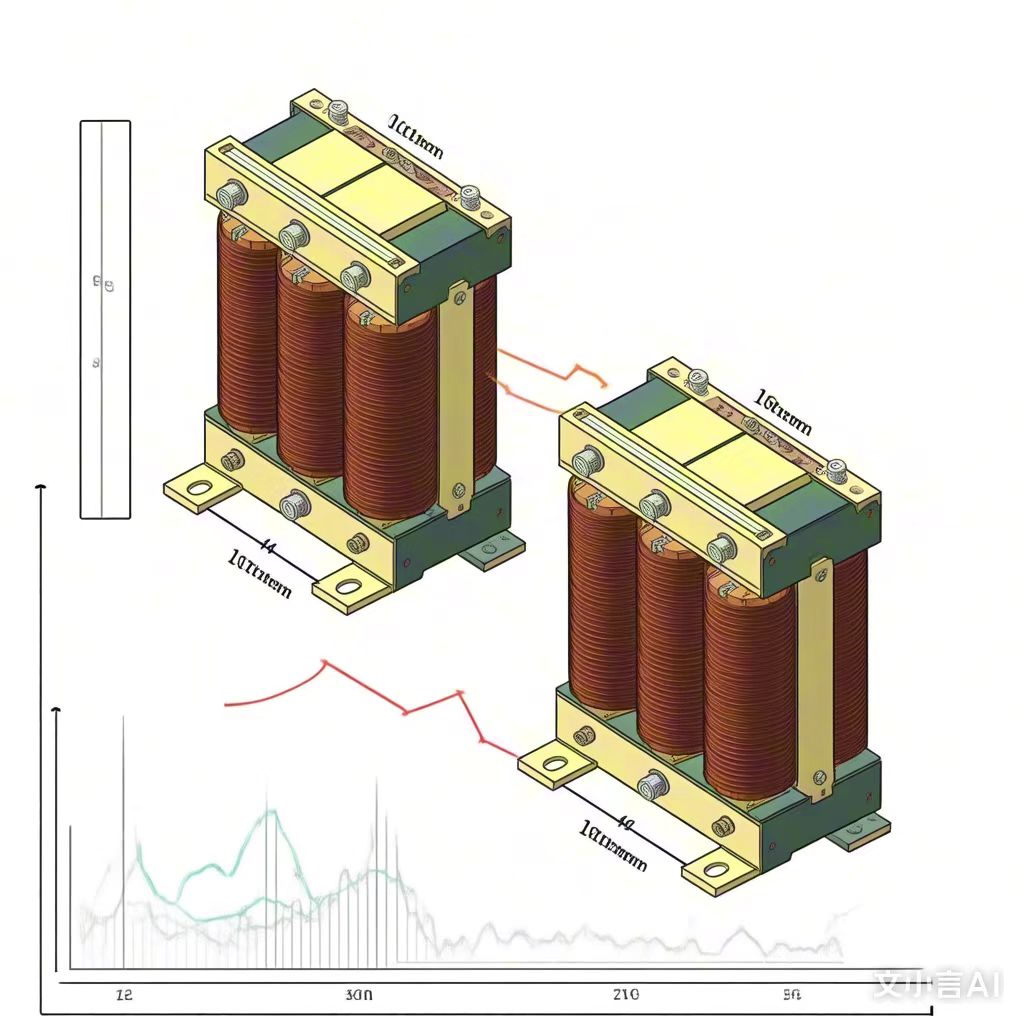
🔍 Key Components of a Power Transformer
| Component | Function |
|---|---|
| Core | Provides magnetic path to transfer energy between windings |
| Windings (Coils) | Conductors where input (primary) and output (secondary) voltages flow |
| Insulation | Electrically isolates windings and prevents short circuits |
| Cooling System | Maintains safe temperature (e.g., oil or air cooling) |
| Conservator Tank | Manages thermal expansion of insulating oil |
| Buchholz Relay | Detects gas or oil movement due to faults inside the transformer |
| Tap Changer | Adjusts voltage ratio to maintain output within required limits |
🔄 Step-Up vs. Step-Down Operation
| Type | Used For | Primary Voltage | Secondary Voltage |
|---|---|---|---|
| Step-Up | At generation stations | Lower | Higher |
| Step-Down | At substations and distribution level | Higher | Lower |
Step-up transformers are used at generation points to raise voltage for long-distance transmission (e.g., from 11kV to 400kV).
Step-down transformers reduce high voltages to safer levels (e.g., from 132kV to 11kV or 400V) for industrial and residential use.
🔬 Energy Conversion Process Inside the Transformer
- AC voltage enters primary winding
- Alternating magnetic flux is created in the core
- Magnetic flux links to secondary winding
- Induced voltage appears in the secondary winding
- Load receives stepped-up or stepped-down voltage
🔥 Cooling Systems for High Efficiency
Power transformers generate heat due to copper losses (I²R) and core losses (hysteresis + eddy currents). Cooling systems are critical.
| Cooling Method | Details | Used In |
|---|---|---|
| ONAN (Oil Natural Air Natural) | Uses natural convection of oil and air | Small/medium transformers |
| ONAF (Oil Natural Air Forced) | Adds fans for air movement over radiators | Medium/large transformers |
| OFAF (Oil Forced Air Forced) | Oil and air both circulated by pumps/fans | Large transmission units |
| Dry-Type Cooling | Air-based (no oil), used in indoor or small applications | Hospitals, indoor systems |
All power transformers use oil for insulation and cooling.False
Not all transformers use oil; dry-type transformers use air or resin insulation and are common in indoor applications.
📈 Voltage and Capacity Ranges
| Voltage Class | Typical Range | Application |
|---|---|---|
| Medium Voltage (MV) | 1kV – 35kV | Local distribution |
| High Voltage (HV) | 66kV – 220kV | Regional transmission |
| Extra High Voltage (EHV) | 220kV – 765kV | Long-distance transmission |
| Power Capacity | Typical Range | Application |
|---|---|---|
| Small | < 10 MVA | Commercial/Institutional |
| Medium | 10 – 100 MVA | Utility substations |
| Large | > 100 MVA | Power stations, national grid |
⚙️ Operation Chart: Power Transformer Process Flow
AC Input → Primary Coil → Magnetic Core → Secondary Coil → AC Output
         ↘ Core Losses ↙           ↘ Copper Losses ↙ → Heat → Cooling System
🏭 Use Cases Across Power Systems
| Sector | Transformer Role |
|---|---|
| Power Generation | Step-up transformer at the output of generator |
| Transmission | High-voltage step-down for efficient long-distance delivery |
| Distribution | Medium to low voltage step-down for consumer delivery |
| Industrial Plants | Supplies customized voltage for high-load machines |
| Hospitals & Data Centers | Ensures voltage stability and isolation for sensitive loads |
What Is an Inverter and What Is Its Main Role?
In today’s fast-evolving energy systems—especially with the rise of solar power, wind energy, and mobile technology—the ability to convert electrical energy efficiently and precisely is vital. One of the core devices that makes this possible is the inverter. Many consumers interact with inverters daily—whether in solar systems, battery backups, or electric vehicles—often without realizing it. When an inverter fails or is improperly matched to the system, power reliability, equipment longevity, and safety are all compromised. This article explores in detail what an inverter is, how it works, and why it is critical across diverse applications.
An inverter is an electronic device that converts direct current (DC) electricity into alternating current (AC). Its main role is to enable the use of DC power sources—such as batteries or solar panels—in systems that require AC power, such as household appliances, grid systems, and industrial machinery.
Understanding inverters is essential for solar engineers, power system designers, facility operators, and residential users seeking energy independence and efficiency.
An inverter can convert DC electricity into AC to power household appliances.True
Inverters are designed to provide AC output from DC sources, enabling compatibility with appliances and the electrical grid.
Inverters are often called the “brains” of modern energy systems—especially off-grid and hybrid systems—because they control and modulate how energy is distributed, used, or fed back to the grid.
⚡ How Does an Inverter Work?
Inverters operate using semiconductor-based switching circuits that convert DC (direct current)—which flows in one direction—to AC (alternating current)—which changes direction cyclically.
Stages of Conversion:
- Input Stage (DC) – Voltage from a battery, solar panel, or fuel cell.
- Oscillator Circuit – Converts DC into a series of high-frequency pulses.
- Switching Transistors (e.g., IGBTs/MOSFETs) – Shape the pulse width to simulate AC.
- Transformer/Filter Stage – Smooths the output waveform into a pure sine wave or modified sine wave.
- Output Stage (AC) – Usable electricity at desired voltage and frequency (e.g., 230V, 50Hz or 120V, 60Hz).
🛠 Types of Inverters by Output Waveform
| Inverter Type | Output Waveform | Typical Use Case |
|---|---|---|
| Pure Sine Wave Inverter | Clean sinusoidal AC | Sensitive electronics, medical equipment, grid use |
| Modified Sine Wave | Blocky waveform | Basic appliances, fans, lights |
| Square Wave Inverter | Square waveform | Rarely used; harsh on electronics |
All inverters produce pure sine wave AC output.False
Some inverters produce modified or square wave outputs, which are less suitable for sensitive equipment.
🔌 Why Is an Inverter Necessary?
Most renewable energy sources (like solar panels) and storage systems (like batteries) produce DC electricity. However, most home and industrial appliances run on AC power. Inverters bridge this gap.
| DC Source | Application Without Inverter | With Inverter |
|---|---|---|
| Solar Panels | Charge batteries only | Power homes or send power to the grid |
| Batteries | Low-voltage DC output only | AC output usable by appliances |
| Electric Vehicles | Battery powers motor (DC-AC) | Drive systems with AC motors |
⚙️ Core Functions of an Inverter
| Function | Explanation |
|---|---|
| DC to AC Conversion | Converts stored or generated DC into usable AC |
| Voltage and Frequency Control | Regulates output to match grid or appliance requirements |
| Synchronization with Grid | Aligns output AC waveform to match grid phase and voltage for feed-in purposes |
| MPPT (in solar inverters) | Optimizes power output from solar panels |
| Battery Management | Manages charge/discharge cycles in hybrid systems |
🔋 Key Applications of Inverters
| Sector | Application Example |
|---|---|
| Residential | Solar rooftop systems, battery backup (UPS) |
| Industrial | Variable frequency drives (VFDs), automation equipment |
| Commercial | Office backup systems, telecom towers |
| Transportation | EVs, railway systems, marine electronics |
| Renewable Energy | Solar farms, wind turbines, hybrid microgrids |
🧩 Technical Breakdown of Solar Inverter System
Solar Panel (DC) → MPPT Charge Controller → Inverter → AC Load/Grid
                                  ↑
Battery Bank (DC)- MPPT (Maximum Power Point Tracking) ensures optimal solar power harvesting
- Inverter provides 230V/120V AC to appliances
- Grid-Tied Inverters allow reverse feeding to the utility grid
📈 Performance Metrics to Consider
| Specification | Importance |
|---|---|
| Efficiency (%) | Determines energy losses during conversion (aim for >95%) |
| Surge Capacity | Handles short bursts of high demand (e.g., motor startup) |
| Waveform Quality | Pure sine wave is safest for sensitive electronics |
| Input Voltage Range | Must match battery or panel configuration |
| Output Voltage/Freq | Must match local AC standard (e.g., 230V/50Hz or 120V/60Hz) |
🌱 Inverters in the Green Energy Transition
Inverters are pivotal to the clean energy transition. Without them, solar and wind energy would be largely incompatible with traditional AC-based infrastructure.
- Grid-Tied Inverters feed renewable energy back to utilities, reducing fossil fuel dependency
- Off-Grid Inverters allow independent, resilient systems for remote areas
- Hybrid Inverters combine solar, battery, and grid for 24/7 energy availability
How Do the Working Principles of a Transformer and an Inverter Differ?
Power conversion technologies are vital to modern electricity systems, yet they often confuse users when discussed side-by-side. Transformers and inverters are both used to change the form of electrical energy—but in fundamentally different ways. Misunderstanding their principles can lead to poor equipment integration, inefficient system performance, or even unsafe configurations. Whether designing a solar microgrid or installing industrial automation, knowing the core difference in how these two devices work is essential.
The working principle of a transformer is based on electromagnetic induction and it converts AC voltage levels, while an inverter works by using semiconductor switches to convert DC to AC. Transformers require alternating current to function and do not generate electricity; inverters actively switch DC into AC using power electronics.
Understanding these principles helps system designers, electricians, and engineers select the correct technology for voltage conversion, grid synchronization, or renewable integration.
Transformers can convert DC into AC.False
Transformers rely on alternating current to induce voltage through magnetic flux and cannot operate with direct current.
Though both are used in power systems, their operational mechanisms, input/output types, and use cases differ significantly.
🔁 Working Principle of a Transformer: Electromagnetic Induction
A transformer is a passive, static device that transfers electrical energy between two or more circuits through mutual induction. It does not create or convert current types—only adjusts voltage and current levels of existing AC (alternating current).
How It Works:
- AC Input to Primary Coil – Alternating current flows through the primary winding.
- Magnetic Field Creation – AC current creates a changing magnetic field in the core.
- Induced EMF in Secondary – The changing magnetic flux induces voltage in the secondary winding.
- Voltage Transformation – Based on turns ratio, the output voltage is stepped up or down.
Key Features:
| Aspect | Transformer |
|---|---|
| Input Type | AC Only |
| Output Type | AC |
| Energy Conversion | Voltage/Current Change Only |
| Working Mechanism | Magnetic Induction |
| Main Components | Coils (windings), magnetic core |
Primary Coil (AC) → Magnetic Field → Secondary Coil (AC, transformed voltage)🔁 Working Principle of an Inverter: Power Electronics and Switching
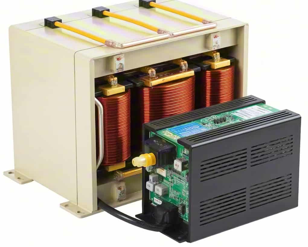
An inverter is an active power electronic device that converts DC (direct current) into AC. It uses fast-switching semiconductors (like MOSFETs or IGBTs) and control circuits to synthesize an AC waveform from a DC source.
How It Works:
- DC Input from Battery/Solar – Supplied by a battery, solar panel, or rectifier.
- Oscillator/Controller – Generates high-frequency signals or modulated waveforms.
- Switching Circuit – Semiconductor switches open and close rapidly to alternate the current.
- Wave Shaping – Output is filtered to generate sine or modified sine AC waveform.
- AC Output to Loads/Grid – Usable for AC equipment or grid feeding.
Key Features:
| Aspect | Inverter |
|---|---|
| Input Type | DC Only |
| Output Type | AC |
| Energy Conversion | Converts DC to AC |
| Working Mechanism | Electronic Switching + Waveform Synthesis |
| Main Components | Switches, controller, filters |
DC Source → Oscillator → Switches → Filter → AC Output⚙️ Technical Comparison Table
| Feature | Transformer | Inverter |
|---|---|---|
| Input Type | AC only | DC only |
| Output Type | AC (converted voltage) | AC (generated from DC) |
| Conversion Type | Voltage level conversion | Current type conversion (DC to AC) |
| Energy Transfer Mechanism | Magnetic induction | Power semiconductor switching |
| Output Waveform | Matches input waveform | Synthesized waveform (sine, modified, square) |
| Frequency Dependence | Input frequency passed through | Output frequency is adjustable |
| Grid Integration Role | Voltage step-up/down (e.g., 11kV to 400kV) | DC-based solar/battery grid connection |
| Passive or Active Device | Passive (no external control needed) | Active (controlled via circuitry) |
Inverters work through electromagnetic induction like transformers.False
Inverters use semiconductor switching and waveform generation, not magnetic flux.
📊 Use Case Alignment
| Application | Needs AC-AC Conversion | Needs DC-AC Conversion |
|---|---|---|
| Power Transmission Grid | ✔ (Transformers step up/down AC voltage) | ✘ |
| Off-Grid Solar Homes | ✘ | ✔ (Inverter required for AC output) |
| Electric Vehicles (Drive) | ✘ | ✔ (Batteries to AC motors) |
| Appliance Voltage Adapters | ✔ (AC-AC voltage conversion) | ✘ |
| Battery Backup Systems | ✘ | ✔ (DC battery to AC appliances) |
🔋 Complementary Use of Inverters and Transformers
In many systems—especially renewable energy setups—both devices are used together:
- Solar Panel (DC) → Inverter (DC to AC) → Transformer (Step up AC voltage) → Grid or AC Load
This combined configuration enables:
- Proper voltage matching for grid injection
- Safe long-distance transmission
- Seamless integration of storage and generation
🧠 Engineering Insights: When to Use Which?
Use a Transformer when:
- You need to change AC voltage levels
- Frequency and current type are already correct
- You are designing a substation, grid interface, or industrial machine
Use an Inverter when:
- You have a DC source (solar, battery)
- You need to produce AC power
- You are building off-grid systems, battery backup, or EVs
What Are the Typical Applications of Transformers and Inverters?
Electricity doesn’t reach homes, factories, or digital devices in its original generation form. It must be converted, shaped, and delivered safely and efficiently. That’s where transformers and inverters come in—two essential but fundamentally different devices. When misunderstood or improperly applied, they can lead to malfunctioning equipment, energy losses, or dangerous scenarios. Knowing where and how each device is used will help anyone involved in energy systems make the right decisions.
Transformers are typically used in AC power systems for stepping voltage up or down, essential for transmission and distribution; inverters are widely used where DC power needs to be converted into usable AC, especially in renewable energy, battery backup, and electric vehicle systems.
This article gives a comprehensive overview of where each device fits into real-world systems, helping readers apply the right component in residential, industrial, renewable, or digital electronics settings.
Inverters are primarily used to convert AC power into DC power.False
Inverters are used to convert DC power into AC, not the reverse. The reverse operation is done by a rectifier.
🔌 Real-World Applications of Transformers
Transformers are passive devices used to modify AC voltage based on magnetic induction. Their uses span from large-scale power transmission to precision electronics.
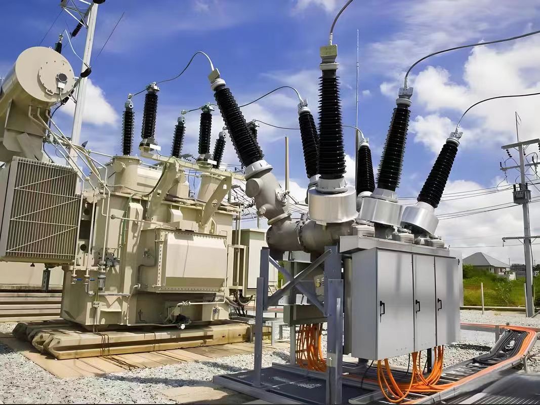
1. Power Transmission and Distribution (Utility-Scale)
- Generation Site: Step-up transformers (e.g., 13.8 kV → 220 kV) for efficient long-distance transmission.
- Substations: Step-down transformers (e.g., 220 kV → 33 kV or 11 kV) for regional grids.
- Pole-Mounted Units: Local voltage reduction for residential homes (e.g., 11 kV → 240V).
2. Industrial Power Systems
-
Used in factories, data centers, and chemical plants to:
- Supply multiple voltage levels to machines.
- Isolate circuits for safety.
- Feed control systems, furnaces, and motors.
3. Low-Voltage Applications
- Control Transformers: Used in automation panels and HVAC controls (e.g., 240V → 24V).
- Audio Transformers: In sound systems for impedance matching and signal isolation.
- Medical Equipment: Provide isolated, stable voltage for imaging or life-support systems.
Transformer Applications Table
| Application | Transformer Type | Voltage Role |
|---|---|---|
| Grid Transmission | Step-Up Transformer | Boost voltage for long-distance |
| Regional Distribution | Step-Down Transformer | Reduce voltage for local supply |
| Industrial Equipment | Isolation/Control Transformer | Provide safe and controlled voltage |
| Audio Systems | Audio Transformer | Match impedance and eliminate noise |
| Medical Equipment | Medical-Grade Transformer | Provide isolation and reliability |
⚡ Practical Applications of Inverters
Inverters are active power electronics devices that convert DC to AC, commonly used where the original power source is DC, or stored energy must be inverted to feed AC systems.
1. Solar and Renewable Energy Systems
-
Solar panels produce DC; inverters convert this to grid-compatible AC.
- Grid-tied inverters synchronize with utility voltage and frequency.
- Hybrid inverters integrate solar, battery, and grid input.
2. Uninterruptible Power Supplies (UPS)
- Converts battery-stored DC power to AC during a power outage.
- Ensures stable power to servers, hospitals, telecom, and banks.
3. Electric Vehicles (EVs)
- Inverters convert the DC from batteries to AC to power traction motors.
- Enable variable frequency and voltage for smooth acceleration.
4. Consumer Electronics and Appliances
- Portable power stations use inverters for 120V/240V AC output.
- Laptop adapters and TVs often include miniature inverters for voltage and frequency regulation.
5. Motor Drives and Industrial Automation
- Variable Frequency Drives (VFDs) use inverters to control motor speed and torque.
- Found in conveyors, fans, pumps, and robotics.
Inverter Applications Table
| Application | Inverter Type | Function |
|---|---|---|
| Solar Power Systems | Grid-Tie / Hybrid | DC → AC for home/grid |
| Backup Power Systems (UPS) | Pure Sine Wave Inverter | Battery DC → AC for emergency loads |
| Electric Vehicles | Traction Inverter | Drive AC motor using DC battery |
| Consumer Electronics | Micro Inverter | Provides AC from battery or DC adapter |
| Industrial VFDs | Industrial Inverter | Modulate motor voltage/frequency |
🔄 Use Case Comparison: Transformers vs. Inverters
| Feature | Transformer | Inverter |
|---|---|---|
| Voltage Conversion | AC-AC only | DC-AC only |
| Type of Energy | No type change (AC remains AC) | Converts energy type (DC to AC) |
| Primary Use | Grid distribution and AC systems | Renewable systems, EVs, battery backups |
| Key Component | Magnetic core and windings | Power electronics (MOSFETs, IGBTs) |
| Power Directionality | Passive (no direction change) | Active (power flow controlled) |
Transformers and inverters can replace each other in any power application.False
Transformers and inverters have distinct purposes and are not interchangeable—transformers require AC, inverters require DC.
🧠 Case Study Insights
🌞 Solar Rooftop System:
-
Components:
- Solar Panel (DC)
- Inverter: Converts DC to AC
- Transformer: Steps up voltage for grid supply
🏭 Factory Automation:
-
Components:
- Grid Supply (AC)
- Transformer: 480V to 120V control voltage
- VFD with Inverter: Controls AC motor speed
🚗 Electric Vehicle:
-
Components:
- Battery (DC)
- Inverter: Feeds AC motor
- Transformer (On-Board Charger): May step-down AC voltage during charging
Can Transformers and Inverters Be Used Together in a Power System?
Modern power systems are evolving rapidly due to the growing demand for efficiency, renewable integration, and decentralized generation. However, many users struggle to understand how transformers, which manage voltage levels in AC systems, and inverters, which convert DC to AC, interact in hybrid or integrated environments. Without proper coordination between these two, power quality issues, equipment failures, and system inefficiencies can arise. The good news? Transformers and inverters can—and often must—work together in advanced energy systems. This article explains how and why.
Transformers and inverters can be used together in a power system to efficiently manage energy flow between AC and DC sources, adjust voltage levels, and ensure compatibility with the utility grid or end-use devices. This is especially common in systems involving solar panels, battery storage, and electric vehicles.
Understanding how these devices complement each other allows engineers, facility managers, and homeowners to build more resilient and energy-efficient power systems.
Transformers and inverters perform the same electrical function in power systems.False
Transformers alter AC voltage levels, while inverters convert DC to AC. Their electrical functions are distinct but complementary.
🔄 Integration Overview: Where Transformers and Inverters Interact
DC to AC Pathway
-
DC Source (e.g., Solar Panel, Battery) → Inverter → Transformer → Load/Grid
- Inverter converts DC to AC at a standard output (e.g., 240V).
- Transformer adjusts this AC voltage to match grid or equipment requirements (e.g., stepping up to 11kV for grid feed-in).
AC to DC Pathway (Bidirectional Systems)
-
Grid/Transformer → Rectifier → Battery → Inverter → Load
- Used in backup or hybrid renewable systems.
- Transformer steps down utility AC voltage.
- Rectifier converts AC to DC to charge battery.
- Inverter provides clean AC during outages or peak times.
🔌 Common Application Scenarios Where Both Are Required
🌞 Solar PV + Battery Hybrid System
| Component | Function |
|---|---|
| Solar Panels (DC) | Primary renewable energy source |
| Inverter | Converts DC to AC |
| Transformer | Steps up AC for grid or down for home |
| Battery Storage (DC) | Stores excess energy |
| Load/Grid | Receives conditioned, correct-voltage AC |
Use case: A rooftop solar system uses an inverter to generate AC from panels, and a transformer to feed this AC into the local grid at 11kV.
🏭 Industrial VFD System
| Component | Function |
|---|---|
| Power Transformer | Supplies medium voltage (MV) |
| VFD Inverter | Converts MV AC to variable-frequency AC |
| Motor | Drives equipment like conveyors/fans |
Use case: A factory has a 33kV supply stepped down to 415V using a transformer, then the VFD's inverter section modulates frequency and voltage to control motor speed.
🏠 Home Solar with Backup
| Component | Function |
|---|---|
| Transformer | Steps down grid voltage (e.g., 11kV→240V) |
| Inverter | Runs home loads from solar or batteries |
| Battery Bank (DC) | Stores energy during the day |
Use case: During outages, an inverter provides AC from battery, and grid power is later stepped down by the utility’s distribution transformer.
⚙️ Electrical Interplay: Technical Diagram
| Flow | Device Involved | Function |
|---|---|---|
| Solar DC → AC | Inverter | Converts renewable DC to grid-compatible AC |
| Inverter AC → Grid-Compatible AC | Transformer (step-up) | Matches grid voltage (e.g., 240V → 11kV) |
| Grid AC → Appliance AC | Transformer (step-down) | Reduces high voltage for end-use loads |
| Battery DC → Backup AC | Inverter | Maintains AC during grid failure |
📉 Power Quality Considerations
When integrating transformers and inverters, it's critical to ensure:
- Harmonic Distortion Control: Inverters can produce harmonics; transformer impedance helps dampen these effects.
- Voltage Matching: Output from inverter must match transformer input rating.
- Grounding Compatibility: Ensure safe and compliant earthing configurations.
- Isolation: Transformers offer galvanic isolation that inverters alone may not provide.
Transformers provide isolation while inverters only perform voltage conversion.True
Transformers inherently provide electrical isolation via magnetic coupling, while inverters typically do not unless designed with isolation.
🛠️ Smart Grid and Advanced Energy Use Cases
📡 Smart Metering and Grid-Interactive Systems
- Transformer manages bidirectional energy at grid interface.
- Inverter communicates real-time power flow for dynamic demand response.
🚗 EV Charging Infrastructure
- Grid transformer delivers AC power at standard voltage.
- On-board inverter in vehicle converts AC to charge DC battery.
🏢 Microgrids
-
Use both to balance multiple sources:
- AC from utility (transformed)
- DC from solar (inverted)
- AC output to internal grid (transformed again)
📊 Efficiency Considerations
| Aspect | Transformer | Inverter |
|---|---|---|
| Efficiency | Up to 99% (passive device) | 92–98% (active, load-dependent) |
| Energy Conversion | AC voltage level change | DC to AC conversion |
| Maintenance Needs | Low (if oil and temp monitored) | Moderate (firmware, cooling required) |
| Lifespan | 20–40 years | 10–15 years |
What Are the Efficiency and Maintenance Differences Between Transformers and Inverters?
When planning a power system, especially one involving renewable energy, industrial automation, or critical infrastructure, choosing between transformers and inverters—or determining how they work together—requires a deep understanding of performance and upkeep. Many users mistakenly assume both devices are interchangeable or require similar care. In fact, transformers and inverters differ significantly in both efficiency and maintenance, which affects lifecycle cost, reliability, and system design strategy. This article provides a complete breakdown of those differences to help you make better power system decisions.
Transformers generally operate with higher efficiency (often >98%) and require minimal maintenance, whereas inverters have slightly lower efficiency (92–98%) and require regular maintenance due to active electronic components and software-based control. These differences are due to their respective designs—passive vs. active—and their roles in converting or conditioning power.
Knowing this distinction allows engineers and operators to better allocate resources and improve long-term system reliability.
Inverters are passive devices like transformers and require very little maintenance.False
Inverters are active electronic devices with software, switches, and cooling systems that require regular maintenance.
⚙️ Fundamental Design Differences That Affect Efficiency and Maintenance
| Attribute | Transformer | Inverter |
|---|---|---|
| Type | Passive (electromagnetic) | Active (electronic + software) |
| Power Conversion | AC-AC voltage level change | DC-AC or AC-DC conversion |
| Internal Components | Coils, core, insulation | Power semiconductors, capacitors, microcontrollers |
| Energy Storage | None | Some models include capacitors or battery buffers |
| Operation Type | Continuous | Intermittent or pulse-width modulated |
Transformers are simpler, with fewer failure points, while inverters are more complex and rely heavily on electronics, cooling, and firmware updates.
🔋 Efficiency Comparison: Real-World Data
Transformer Efficiency
| Type | Efficiency Range |
|---|---|
| Distribution (<10 MVA) | 97% – 99.5% |
| Power (>10 MVA) | 98.5% – 99.8% |
| Dry-Type | 95% – 98% |
Inverter Efficiency
| Application | Efficiency Range |
|---|---|
| Residential Solar | 95% – 98% |
| Commercial/Industrial | 92% – 97% |
| Off-grid Hybrid | 90% – 96% |
Why the Difference?
Transformers incur only resistive and magnetic losses, which are minimal. In contrast, inverters face:
- Switching losses in transistors (IGBTs, MOSFETs).
- Control overhead due to digital processors.
- Harmonic distortion losses in pulse-width modulation.
Transformers always consume more energy than inverters because they run constantly.False
Transformers are highly efficient passive devices. Inverters, being active devices, typically introduce higher conversion losses.
🧰 Maintenance Requirements and Frequency
Transformer Maintenance Needs
| Task | Frequency | Notes |
|---|---|---|
| Visual inspection | Annually | Check for oil leaks, corrosion |
| Oil testing (for oil-type) | Every 2–3 years | Analyze for moisture, acidity, dielectric strength |
| Bushing inspection | Annually | Look for cracks, contamination |
| Thermal imaging | Every 2–3 years | Detect hot spots |
| Cleaning (dry-type) | 1–2 times/year | Dust and debris removal |
Transformers can operate reliably for 25–40 years with minimal intervention if monitored properly.
Inverter Maintenance Needs
| Task | Frequency | Notes |
|---|---|---|
| Firmware/software updates | As needed | Often remotely pushed by manufacturer |
| Heat sink & fan cleaning | Quarterly/biannual | Prevents thermal damage |
| Capacitor health check | Annually | Critical to performance and lifespan |
| Grid/communication sync check | Monthly/quarterly | Ensures proper smart grid functionality |
| Electrical connection testing | Annually | Detect loose or oxidized terminals |
Inverters generally last 10–15 years before full replacement is needed—though modular models may extend this.
📉 Downtime and Lifecycle Considerations
| Factor | Transformer | Inverter |
|---|---|---|
| Typical Lifespan | 25–40 years | 10–15 years |
| Mean Time to Repair | Longer repair, lower frequency | Shorter repair, more frequent issues |
| Replacement Cycle | Rare, based on insulation or core aging | More frequent due to electronics aging |
| Failure Risk | Low if properly sized and installed | Moderate due to component complexity |
Transformers are more “fit-and-forget,” while inverters require ongoing operational management and firmware support.
🔄 Comparative Lifecycle Chart
| Aspect | Transformer | Inverter |
|---|---|---|
| Initial Cost | Moderate to high | Moderate |
| Operating Cost | Very low | Moderate |
| Routine Maintenance Cost | Low | Higher |
| Downtime Risk | Low | Medium to High |
| Lifecycle Serviceability | Very high | Medium |
| Replacement Timeline | 25–40 years | 10–15 years |
🛠 Real-World Example: Solar Power Plant
| Component | Maintenance Task | Impact if Ignored |
|---|---|---|
| Transformer | Oil dielectric testing | Core damage, eventual failure |
| Inverter | Fan cleaning, firmware updates | Overheating, grid desync, total shutdown |
| Combined Failure | Both offline | Total loss of solar output |
This shows that while both are essential, inverters need more attention to detail to ensure system uptime.
Conclusion
While power transformers and inverters are both essential components in modern power systems, their functions are distinctly different. Transformers are designed to efficiently transfer electrical energy at different voltage levels within AC systems, primarily in utility and industrial networks. In contrast, inverters focus on converting DC to AC power, enabling the integration of energy storage, solar generation, and electronic applications. Understanding their differences not only aids in proper system design but also enhances energy efficiency, safety, and sustainability. By recognizing where and how to use each device, professionals can make informed decisions in both traditional and renewable power infrastructures.
FAQ
Q1: What is the primary function of a power transformer vs an inverter?
A1: A power transformer transfers electrical energy between voltage levels in AC form, usually for transmission and distribution.
An inverter converts DC (Direct Current) into AC (Alternating Current), allowing devices powered by batteries or solar panels to connect to AC-powered systems.
Q2: What type of energy conversion do transformers and inverters perform?
A2: Transformer: Converts voltage levels within AC circuits (e.g., 11kV to 220V).
Inverter: Converts DC to AC, enabling the use of DC power sources in AC-based systems (e.g., solar inverters, UPS systems).
Q3: Where are power transformers and inverters commonly used?
A3: Power Transformers: Found in power grids, substations, and industrial settings to manage high-voltage electricity.
Inverters: Used in solar systems, battery backups, electric vehicles, and home UPS systems to convert stored DC power into usable AC power.
Q4: Can an inverter and transformer be used together?
A4: Yes. In many systems—especially solar and renewable setups—inverters are paired with transformers to step up or step down the AC voltage after conversion from DC. Some inverter units even include internal transformers to adjust output voltage as needed.
Q5: Which device should I use—transformer or inverter?
A5: Choose a transformer if you need to change AC voltage levels without altering current type.
Use an inverter if you need to convert DC power to AC for compatibility with standard devices or the power grid.
Your choice depends on your energy source and application requirements.
References
"Difference Between Inverter and Transformer" – https://www.electrical4u.com/difference-between-inverter-and-transformer
"How Do Inverters Work?" – https://www.energy.gov/eere/solar/articles/what-inverter
"Power Transformers Explained" – https://new.abb.com/transformers
"Inverter Basics and Applications" – https://www.solarreviews.com/blog/how-does-an-inverter-work
"IEEE: Inverter System Design" – https://ieeexplore.ieee.org/document/7407358
"Transformer vs Inverter Functionality" – https://www.gegridsolutions.com/knowledge-center
"Power Electronics and Converters" – https://www.powermag.com/power-electronics-fundamentals
"Solar Inverters vs Transformers" – https://www.sciencedirect.com/inverter-vs-transformer
"Understanding Grid-Tied Inverters and Transformers" – https://www.cleanenergyreviews.info/blog/grid-tie-inverter-transformer