Power transformers are vital components in electrical power systems, and they are highly vulnerable to lightning strikes, which can cause severe insulation damage, overheating, and even catastrophic failure. Lightning protection is therefore an essential part of transformer design and installation. By implementing proper protective measures, utilities can prevent costly downtime and extend the lifespan of transformers. This article explores the main lightning protection methods for power transformers, how they work, and why they are critical for grid stability.
Why Are Power Transformers Vulnerable to Lightning Strikes?
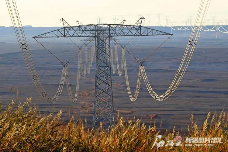
Power transformers are critical to the stability of electric power grids—but they also stand as prime targets during thunderstorms. Their tall metallic structures, high-voltage connections, and outdoor exposure make them particularly vulnerable to lightning strikes. Even a single strike can induce overvoltages, cause catastrophic insulation failure, or disrupt service across wide regions. Understanding this vulnerability is key to protecting transformers and preventing widespread outages.
Power transformers are vulnerable to lightning strikes because they are installed outdoors, often on elevated structures, with direct connections to overhead lines; lightning introduces steep-front transient overvoltages that can exceed the insulation strength of windings and bushings, potentially causing flashover, dielectric breakdown, or permanent damage unless properly protected by surge arresters and grounding systems.
Despite modern protection technologies, lightning remains a top cause of transformer damage globally. This article explains why transformers are so susceptible and what engineering methods are used to defend them.
Power transformers are immune to lightning strikes because of their steel enclosures.False
Steel tanks provide mechanical protection but do not shield windings or insulation from the high-energy surges caused by lightning.
Lightning-induced overvoltages can cause transformer insulation failure if not properly managed.True
Lightning strikes can produce extremely high voltages that surpass insulation coordination limits, leading to internal flashovers or winding damage.
Reasons for Transformer Vulnerability to Lightning
1. Exposure to Overhead Transmission Lines
Transformers are directly connected to HV overhead lines:
- These lines act as conduits for lightning energy
- A strike miles away can propagate surges into the transformer
- Terminal bushings are the first points of entry
| Component | Vulnerability Level | Reason |
|---|---|---|
| HV bushings | High | Direct path for lightning surges |
| Windings | High | Exposed to dielectric stress from surges |
| Tank body | Medium | Induced currents from nearby strikes |
2. Steep Front Transient Overvoltages
Lightning surges have:
- High amplitude: 100–300 kV or more
- Extremely fast rise time: <1 µs
- Can exceed Basic Insulation Level (BIL) of the transformer
Example: A 132 kV transformer has a BIL of \~550 kV. A direct lightning surge can exceed this by several hundred kilovolts, leading to insulation puncture.
3. High Elevation and Isolation
Transformers are often the tallest structures in substations, particularly:
- In rural or open areas
- With rooftop-mounted transformers on buildings
- Near mountain-top installations
These conditions increase lightning strike probability.
4. Weakness in Insulation Coordination
If:
- Surge arresters are improperly rated
- Clearance distances are insufficient
- Grounding paths are high-resistance
Then: - The surge bypasses protective paths
- Energy is forced into transformer insulation
| Protection Element | Risk if Improperly Specified |
|---|---|
| Surge arrester MCOV | Won’t clamp surges fast enough |
| Spark gaps | May fail to arc-over at correct voltage |
| Ground resistance | Surge discharge becomes ineffective |
5. Lack of Regular Maintenance
Over time:
- Surge arresters degrade
- Grounding resistance increases due to corrosion
- Bushing oil or porcelain develops micro-cracks
This reduces protection integrity, increasing risk of damage during storms.
Lightning Damage Mechanisms in Transformers
A. Bushing Flashover
- Occurs when voltage exceeds air-side insulation
- Can cause carbonization, leading to permanent leakage paths
B. Internal Winding Failure
- Surges cause voltage stress across adjacent windings
- Insulation may puncture or delaminate, leading to turn-to-turn faults
C. Tank Induced Currents
- Nearby strikes induce currents in tank steel
- May cause eddy current heating, or affect grounding connections
D. Partial Discharge Initiation
- Surges initiate corona discharges within paper/oil insulation
- Leads to long-term degradation and aging acceleration
Case Example: 220 kV Transformer Lightning Incident
- Location: Coastal substation in SE Asia
- Problem: Summer lightning storm caused trip of one 220/132 kV transformer
-
Post-incident findings:
- Surge arrester lead broken
- HV bushing flashover mark visible
- IR values drastically reduced
Downtime: 9 days
Repair cost: Over \$120,000
Root cause: Missing regular arrester testing
Key Protection Strategies Against Lightning
| Protection Method | Description | Effectiveness |
|---|---|---|
| Surge Arresters | Divert surges to earth before entering transformer | High |
| Shield Wires / Masts | Intercept lightning before hitting lines or equipment | High |
| Proper Grounding System | Low-impedance path for surge discharge | High |
| BIL Coordination | Insulation designed above max surge level | Medium-High |
| Wave Traps / Line Reactors | Reduce high-frequency energy | Medium |
| Routine Testing | Check arrester function and grounding integrity | High |
Summary Table: Lightning vs Transformer Defense
| Vulnerability Source | Resulting Threat | Mitigation Measure |
|---|---|---|
| Overhead line coupling | Surge propagation | Line-side arresters |
| Poor grounding | Surge discharge failure | Multi-rod low-resistance grid |
| High rise time surges | BIL breach | Fast-acting MOV arresters |
| Bushing degradation | Flashover and arcing | IR testing, replacement |
| No shielding | Direct strike | Lightning masts, earth wires |
What Role Do Surge Arresters Play in Lightning Protection?
When lightning strikes a power line or substation, it unleashes an enormous surge of energy—hundreds of kilovolts with a rise time of microseconds. This surge, if unchecked, travels through transmission lines and directly threatens sensitive equipment like transformers, circuit breakers, and relays. The first and most crucial line of defense against this destructive force is the surge arrester.
Surge arresters protect transformers from lightning by diverting high-voltage transient overvoltages to ground before they reach the transformer's insulation system, effectively clamping the surge to a safe voltage level. Installed at strategic points—typically near transformer bushings—surge arresters act within microseconds, preventing flashovers, winding failure, and catastrophic equipment damage.
Without surge arresters, even a distant lightning strike on a power line can propagate through the grid and destroy transformer windings or bushings. Understanding the design, function, and placement of surge arresters is vital for ensuring the lightning resilience of any electrical installation.
Surge arresters completely eliminate lightning energy from the system.False
Surge arresters do not eliminate lightning; they safely divert excess energy to ground, limiting voltage exposure to protected equipment.
Surge arresters are designed to activate within microseconds to protect against fast lightning surges.True
Modern metal-oxide surge arresters operate with extremely fast response times, reacting within microseconds to clamp dangerous overvoltages.
How Surge Arresters Work
Surge arresters are non-linear resistive devices—they remain non-conductive at normal system voltages, but instantly become conductive when voltage exceeds a threshold, directing the surge to earth.
Key Operating Steps:
- Lightning or switching surge causes voltage spike
- Arrester detects the overvoltage
- Arrester’s internal metal-oxide varistors (MOVs) conduct the surge current
- Voltage is clamped to a safe level (e.g., 120 kV at 66 kV BIL)
- Surge is discharged into the grounding system
- Arrester returns to non-conducting state immediately after
Types of Surge Arresters Used in Transformer Protection
| Arrester Type | Application | Characteristics |
|---|---|---|
| Station-class arresters | Transmission substations | High energy handling, long lifespan |
| Intermediate-class | MV distribution substations | Moderate protection capacity |
| Distribution-class | Pole-mounted transformers | Compact, cost-effective |
| Line surge arresters | On overhead transmission lines | Protect against backfeed surges |
Metal Oxide Varistor (MOV) arresters are the standard for modern systems due to their fast response and no need for spark gaps.
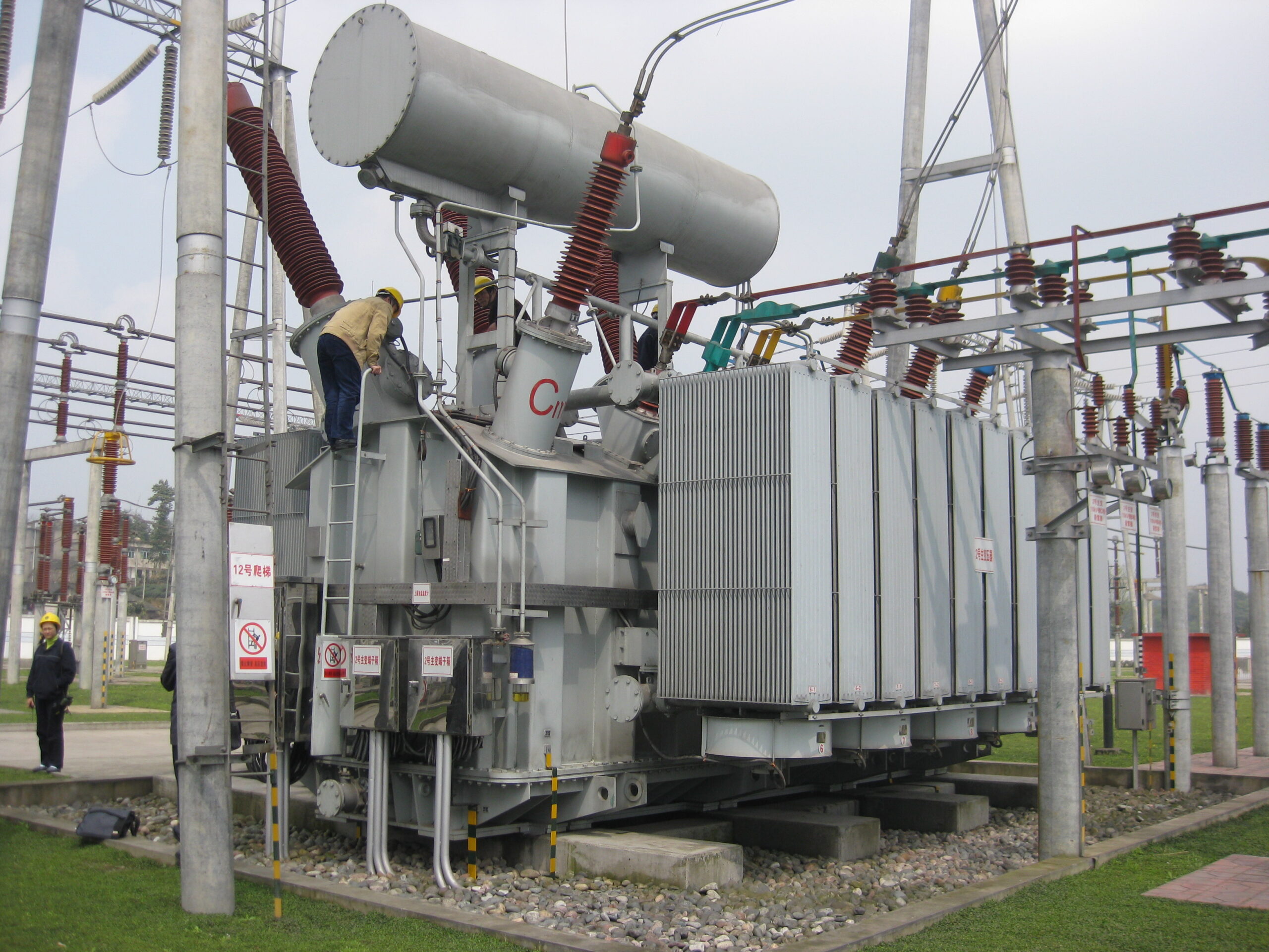
Placement of Surge Arresters Around Transformers
Critical Connection Points:
- At each phase of HV bushing
- Between bushing and incoming line
- Between bushing and transformer tank (for neutral grounding)
- On the LV side if connected to long cable runs
| Location | Purpose |
|---|---|
| Line side of HV bushings | Divert incoming lightning surges |
| Neutral terminal | Protect against overvoltages from earth faults |
| LV side (optional) | Protect from reflected surges or cable resonance |
Ideal Installation Configuration:
- As close to the transformer bushing as possible (≤1 m lead length)
- Short, straight earth conductor for low impedance path
- Mounted with insulated brackets or base-mounted support
Long or coiled connections increase surge impedance and reduce arrester effectiveness.
Electrical Parameters of Surge Arresters
| Parameter | Definition | Example Value (for 132 kV system) |
|---|---|---|
| Maximum Continuous Operating Voltage (MCOV) | Max voltage arrester can withstand continuously | 108 kV |
| Rated Voltage | Maximum surge arrester voltage rating | 132 kV |
| Residual Voltage | Voltage at which arrester clamps the surge | 275 kV |
| Energy Absorption | Total surge energy the arrester can handle | 10–20 kJ/kV |
| Discharge Current Rating | Max current the arrester can handle in one surge | 10–20 kA |
Role in Insulation Coordination
Transformers have insulation ratings (BIL – Basic Insulation Level). Surge arresters ensure that surges never exceed the BIL by clamping surges at a safe level.
| Equipment | Typical BIL | Arrester Clamping Voltage |
|---|---|---|
| 11 kV Transformer | 95 kV | \~30–40 kV |
| 66 kV Transformer | 250–350 kV | \~120–180 kV |
| 132 kV Transformer | 550 kV | \~275–300 kV |
The gap between BIL and arrester residual voltage must be adequate to protect the transformer even under the worst surge conditions.
Case Study: Surge Arrester Saved Transformer from Lightning Strike
Scenario:
- 220/66 kV transformer in rural substation
- Lightning struck nearby transmission pole
- Surge arrester on R phase of transformer conducted 15.8 kA to ground
- No fault occurred; breaker remained closed
- Post-event inspection: arrester heat marks observed, but transformer fully functional
Conclusion: Arrester successfully protected the bushing and windings by clamping the surge and safely discharging it.
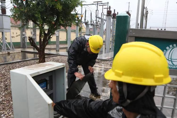
Maintenance and Monitoring of Surge Arresters
- Visual inspection for cracks, contamination, or discharge marks
- Leakage current monitoring for internal aging detection
- Infrared thermography to detect hot spots or internal failures
- Replace arresters showing tracking, oil leaks, or discoloration
| Inspection Interval | Recommended Activity |
|---|---|
| Monthly | Visual and temperature check |
| Annually | Leakage current, insulation testing |
| After lightning event | Full arrester test or replacement |
Summary Table: Surge Arrester Benefits
| Protection Provided | Outcome |
|---|---|
| Lightning surge diversion | Prevents bushing flashover |
| Clamping of overvoltages | Avoids winding insulation breakdown |
| Fast response time | Limits voltage before damage occurs |
| Energy absorption | Handles surge energy safely |
| Insulation coordination | Keeps voltage below transformer BIL |
How Do Shielding Wires and Grounding Systems Help in Transformer Lightning Protection?
When lightning strikes or approaches a substation, the entire site becomes electrically stressed. Without proper shielding and grounding, that surge energy can enter transformer windings, flash over bushings, or even cause explosive failures. While surge arresters handle voltage clamping at terminals, shielding wires and grounding systems serve as the first and last lines of defense, ensuring that lightning never enters the transformer path in the first place—or is quickly and safely dissipated if it does.
Shielding wires protect transformers by physically intercepting direct lightning strikes before they hit critical components, while grounding systems provide low-resistance paths to safely dissipate surge currents into the earth. Together, they reduce strike probability, minimize step and touch potentials, and enhance the performance of surge arresters and other protective devices.
They form an essential part of holistic lightning protection design, particularly in substations, power plants, and exposed rural installations. Without effective shielding and grounding, even the best arresters can be overwhelmed.
Grounding systems are only required for electrical faults, not for lightning protection.False
Grounding is essential for both fault current dissipation and lightning energy discharge; without it, lightning surges can cause dangerous overvoltages and flashovers.
Shielding wires reduce the risk of direct lightning strikes on transformers.True
Properly installed overhead ground wires create an electrostatic shield that protects equipment below from direct strikes.
Role of Shielding Wires in Lightning Protection
What Are Shielding Wires?
- Also called overhead ground wires (OHGW) or earth wires
- Bare conductors strung above energized lines or equipment
- Installed to intercept lightning before it reaches power apparatus
How They Work
- Positioned higher than the transformer bushings and conductors
- When lightning approaches, it preferentially strikes the shielding wire
- The surge current is then diverted through the grounding system
| Shielding Function | Benefit |
|---|---|
| Physical lightning interception | Prevents direct hit on transformer |
| Electrostatic shielding | Reduces voltage gradient near equipment |
| Lightning energy redirection | Guides surge to earth via down-conductors |
Design Considerations
- Must form a protected zone (Rolled Sphere Method)
- Use steel, copper, or aluminum-clad steel for strength and conductivity
- Must be grounded at multiple points (every 200–300 meters)
| Installation Parameter | Typical Value |
|---|---|
| Height above equipment | ≥3–5 meters above top bushing |
| Number of down-conductors | ≥2 per wire at station ends |
| Ground resistance target | ≤1 ohm per downlead |
Grounding Systems: The Critical Surge Exit Path
Purpose of Grounding
- Provide a low-impedance path for lightning and fault currents
- Limit step and touch voltages during surge discharge
- Support surge arrester operation by minimizing voltage rise
Components of a Grounding System
- Earth grid of copper or galvanized steel buried under transformer
- Vertical ground rods or electrodes driven into soil
- Mesh or ring earth connecting all metallic parts (tank, fencing, equipment)
-
Bonding of:
- Transformer tank
- Neutral bushing
- Surge arrester base
- Cable shields
- Support structures
| Component | Role |
|---|---|
| Earth grid mesh | Distributes surge safely over area |
| Ground rods | Provide low-resistance path to soil |
| Bonding conductors | Equalize potential between equipment |
Lightning Discharge Without Grounding:
- Surge current flows into equipment or nearby structures
- Creates dangerous overvoltages, arcing, or shock hazards
- Damages insulation or causes transformer failure
Integration of Shielding, Grounding, and Arresters
When a lightning surge occurs:
- Shielding wire intercepts the strike
- Surge travels down down-conductors to grounding grid
- Residual surge that reaches transformer terminals is clamped by surge arresters
- Arrester discharges surge into ground system
- Transformer remains protected
All three systems—shielding, grounding, arresters—must be coordinated to function effectively.
| Protection Element | Interacts With | Role in Lightning Defense |
|---|---|---|
| Shielding wire | Atmosphere, strike | Diverts lightning above equipment |
| Surge arrester | Transformer terminals | Clamps incoming surge voltage |
| Grounding system | Earth, all devices | Provides surge exit path and safety |
Common Grounding System Failures
| Fault Type | Consequence |
|---|---|
| High soil resistivity | Ineffective surge dissipation |
| Corroded connections | Arcing, unsafe potential rise |
| Single-point grounding | Floating voltages during discharge |
| Poor bonding | Equipment at different voltages |
Regular soil resistivity testing and grid integrity checks are mandatory for substation reliability.
Case Study: Lightning Strike on 33 kV Substation
Incident:
- Lightning struck a transmission pole 400 m from substation
- Surge bypassed poorly bonded shielding system
- Transformer surge arrester clamped, but grounding system had 15-ohm resistance
- Residual voltage damaged LV winding insulation
- Repair downtime: 12 days, cost: \$65,000
Lesson: Incomplete grounding renders surge arresters ineffective—even with proper clamping.
Best Practices for Effective Shielding and Grounding
| Best Practice | Purpose |
|---|---|
| Install shielding wire above top bushing | Create lightning protection zone |
| Use multiple grounding rods per transformer | Lower impedance and ensure redundancy |
| Test ground resistance annually | Detect corrosion or soil moisture change |
| Use CAD-welded (exothermic) joints | Ensure corrosion-free, low-resistance bonds |
| Bond all conductive parts together | Prevent potential difference during surge |
What Is the Importance of Transformer Bushing Protection?
Transformer bushings serve as the critical interface between internal windings and external circuits, enabling safe passage of high-voltage conductors through the transformer's grounded tank. Despite their robust design, bushings are also one of the most vulnerable components in any transformer. Over 30% of transformer failures are directly attributed to bushing failure—often resulting in catastrophic explosions, oil fires, or extended outages. Protecting these bushings is not just good practice—it’s essential to the safe and reliable operation of power systems.
Transformer bushing protection is crucial because bushings are exposed, high-voltage insulation components that are susceptible to electrical surges, thermal stress, mechanical damage, and partial discharge. Effective protection—through surge arresters, condition monitoring, shielding, and routine diagnostics—prevents catastrophic failures, ensures system reliability, and extends transformer life.
In this article, we detail the importance of bushing protection, failure modes, and best practices to ensure safe, uninterrupted operation.
Bushing failures are rare and do not significantly affect transformer reliability.False
Bushing failures are among the top three causes of major transformer failures, often leading to fires or explosions if unprotected.
Surge arresters and bushing monitoring systems help prevent insulation breakdown in bushings.True
These protection systems detect overvoltage stress and insulation degradation early, enabling preventative action before failure.
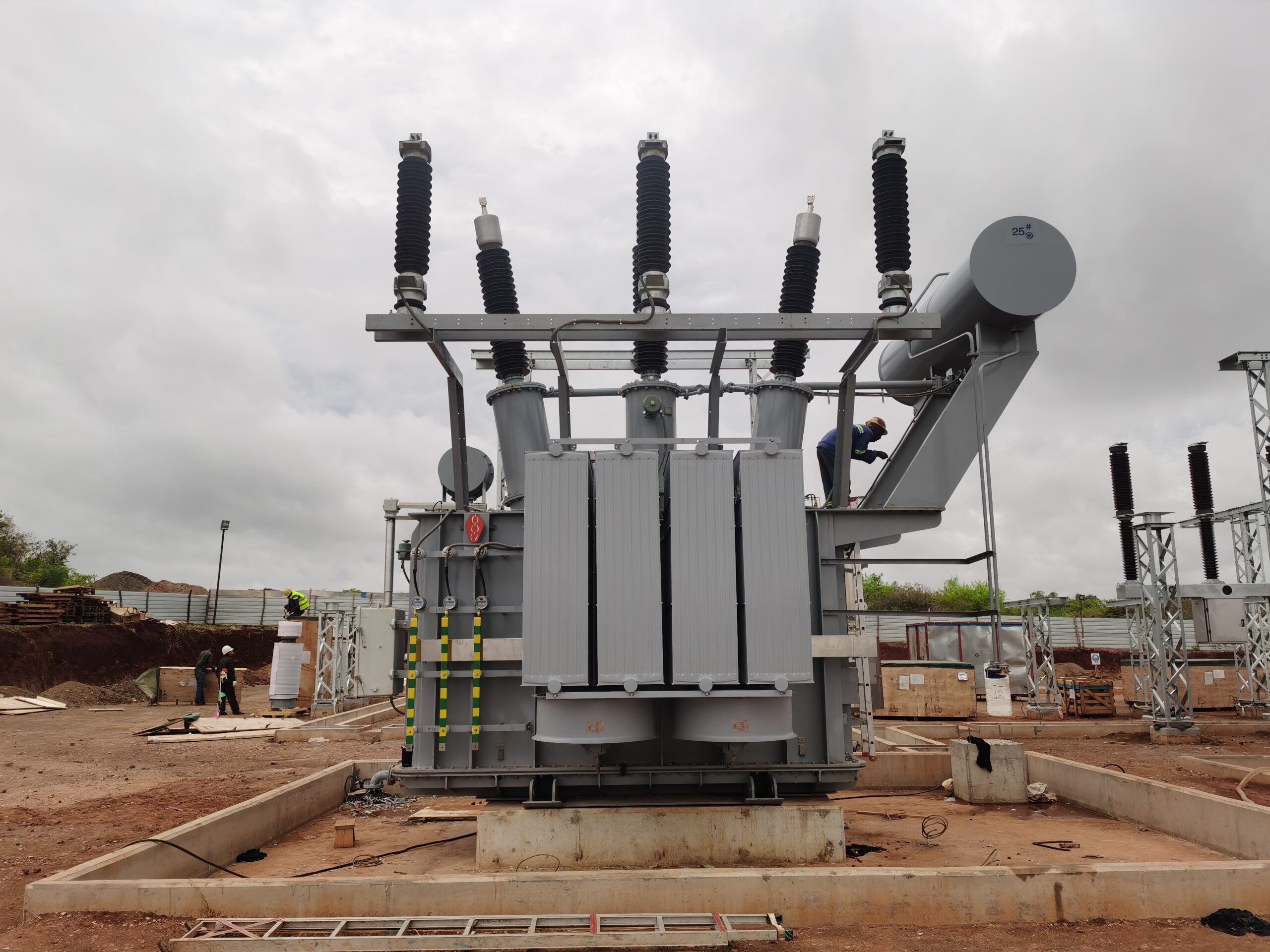
What Are Transformer Bushings?
Bushings are:
- Insulated devices allowing a high-voltage conductor to pass through the grounded transformer tank
- Usually oil-filled capacitor-type for HV applications
- Constructed with porcelain or composite (polymer) insulators
Key Functions:
- Insulate the conductor from the tank
- Withstand electrical, thermal, and mechanical stress
- Provide creepage and clearance for environmental exposure
| Component | Function |
|---|---|
| Central conductor rod | Current carrying path |
| Capacitive layers | Graded insulation to manage voltage stress |
| Porcelain/composite shell | Environmental insulation barrier |
Why Are Bushings So Vulnerable?
1. Electrical Overstress
- Direct lightning strikes or switching surges can exceed insulation design
- Partial discharge initiates microscopic breakdown
- Over time, leads to complete flashover or arc-through
2. Thermal and Aging Stress
- Oil contamination or moisture ingress reduces insulation strength
- High ambient temperatures or overloading accelerate aging
3. Mechanical Damage
- Transportation mishandling
- Vibration during operation
- Physical shock (e.g., crane impact)
4. Pollution and Moisture
-
Outdoor bushings exposed to:
- Industrial pollution (salt, dust, chemicals)
- Wetting from rain or condensation
- Ice formation in cold climates
| Cause | Typical Result |
|---|---|
| Moisture ingress | Dielectric failure and flashover |
| Lightning surge | Puncture of insulation |
| Contaminated surface | Surface tracking and corona discharge |
| Vibration | Loosened internal layers, cracking |
Consequences of Bushing Failure
- Explosion risk due to arc energy and oil ignition
- Transformer downtime (days to weeks)
- Fire hazards in substations or plants
- Collateral damage to nearby equipment
- System-wide blackouts in critical networks
Real-World Example:
A 132 kV bushing failed at a distribution substation in Europe during a thunderstorm. The failure led to an arc-through event, igniting transformer oil. Fire suppression failed. The transformer was a total loss, causing a 48-hour blackout and €1.2M in damages.
Key Methods of Bushing Protection
1. Surge Arresters
- Installed near HV bushings
- Clamp lightning and switching surges before they reach the bushing
- Must be rated correctly and grounded with short leads
2. Capacitance and Power Factor Monitoring
-
Detect insulation degradation through changes in:
- Capacitance (C1/C2 layers)
- Power factor (tan delta)
- Modern online monitoring systems issue early warnings
| Monitoring Parameter | Diagnostic Insight |
|---|---|
| Capacitance drift | Moisture, delamination, or aging |
| Tan delta increase | Internal insulation contamination |
| Partial discharge | Local insulation failure |
3. Visual and Thermal Inspection
- Cracks, chalking, or discoloration on outer shell
- Use infrared cameras to detect hot spots (early sign of resistive heating)
- Corona cameras to detect electrical discharge
4. Routine Offline Testing
- Performed during shutdowns
-
Includes:
- IR (insulation resistance)
- Capacitance and power factor (with DOBLE or similar)
- Oil sampling (for DGA or moisture)
| Test Type | Frequency | Limit Value |
|---|---|---|
| Tan delta (PF) test | Every 2–5 years | <0.5% for HV bushings |
| Capacitance variation | Trend monitoring | <3% change from baseline |
| IR (Megger) test | Annually | >1000 MΩ at 5–10 kV |
Integration with Protection Systems
Bushing monitoring can be integrated into:
- SCADA and RTUs
- Transformer protection relays (e.g., 87T, 64R)
- Automated tripping circuits for dangerous thresholds
Modern systems like ABB’s “MSENSE” or Siemens’ “BMON” provide real-time alerts, enabling predictive maintenance.
Summary Table: Bushing Protection and Risk Mitigation
| Protection Method | Function | Failure Risk Addressed |
|---|---|---|
| Surge arresters | Divert lightning/surge energy | External overvoltage |
| Capacitance/power factor monitor | Detect internal aging or moisture | Internal degradation |
| Visual & infrared inspection | Identify surface damage, hotspots | Surface breakdown, arcing |
| Offline tan delta testing | Benchmark insulation health | Predictive failure detection |
| Ground lead monitoring (C2) | Detect ground fault in capacitor layer | Shorted insulation |
How Does Proper Site Design Improve Lightning Resistance?
Lightning remains one of the leading natural threats to electrical infrastructure, especially in substations and transformer yards. A single lightning strike can result in equipment damage, prolonged outages, fire hazards, and massive repair costs. However, most lightning-related transformer failures are not caused by the lightning itself—but by inadequate site design that fails to properly shield, ground, or divert surge energy. Well-engineered site design is the first and most powerful defense in improving lightning resilience.
Proper site design improves lightning resistance by integrating shielding structures, surge protection coordination, low-resistance grounding networks, adequate equipment spacing, and elevation planning to intercept lightning energy and divert it safely to earth. These elements work together to reduce the probability of direct strikes, suppress overvoltage propagation, and protect critical equipment like transformers, bushings, relays, and switchgear.
From lightning masts to soil resistivity analysis, every design detail plays a role in shielding your power system from atmospheric threats. This article outlines the design principles and standards that make substations lightning-resilient.
Proper site layout and shielding can significantly reduce the chance of direct lightning strikes to transformers.True
Strategically placed shielding masts and overhead ground wires can create protected zones that divert lightning away from sensitive equipment.
Grounding systems are secondary and not critical in lightning protection.False
Grounding systems are essential to safely dissipate lightning energy into the earth; without proper grounding, surge energy can damage equipment or pose a shock hazard.
Key Elements of Lightning-Resistant Site Design
1. Lightning Shielding Structures
- Lightning masts, overhead ground wires, and air terminals are used to intercept lightning.
-
These components must be placed based on:
- Rolling sphere method (usually 30–45 m radius depending on risk level)
- Angle method (e.g., 45° protection cone)
-
Shielding must protect:
- Transformers
- Control panels
- Switchgear
- Overhead incoming lines
| Shielding Method | Description | Zone of Protection |
|---|---|---|
| Lightning mast | Vertical rods intercept lightning | Cylindrical cone (\~45° angle) |
| Shielding wire (OHGW) | Overhead earth wire | Linear or area protection |
| Static wire with downlead | Bonded to grounding grid | Direct surge path to earth |
Design Tip: Install masts so their protection zones overlap, ensuring no equipment is left exposed.
2. Grounding System Design
A proper grounding system is the backbone of lightning protection. It:
- Safely dissipates surge energy from arresters, shielding, and equipment enclosures
- Limits dangerous step and touch voltages
- Enhances surge arrester performance by minimizing ground potential rise
Grounding System Must Include:
- Copper or galvanized steel mesh/grid under entire substation
- Ground rods at regular intervals (5–10 m spacing)
-
Earth mat bonded to:
- Transformer tanks
- Equipment frames
- Cable trays
- Fence (with isolation gap)
| Grounding Design Parameter | Typical Value or Target |
|---|---|
| Ground resistance | <1 ohm (ideal), <5 ohms (acceptable) |
| Rod depth | 2–3 meters |
| Mesh spacing | 3–7 meters |
| Conductor size | 70–120 mm² Cu or equivalent |
3. Surge Protection Coordination
Purpose:
Ensure lightning surges are intercepted and clamped before reaching insulation-sensitive equipment.
Includes:
- Surge arresters at transformer terminals and incoming feeders
- Proper energy rating and residual voltage selection
- Short, straight leads to grounding system
Coordination with Insulation:
- Ensure surge arrester clamping voltage < transformer BIL
- Maintain coordination gap (typ. 20% margin)
| System Voltage | Transformer BIL | Arrester Residual Voltage |
|---|---|---|
| 33 kV | 170 kV | \~90–110 kV |
| 66 kV | 325 kV | \~180–220 kV |
| 132 kV | 550 kV | \~280–330 kV |
4. Equipment Spacing and Layout
Goals:
- Minimize coupling between grounded and ungrounded parts
- Reduce risk of cross-phase flashover
- Improve accessibility for maintenance and safety
Layout Guidelines:
- Keep transformers 5–7 m from fences or structures
- Provide minimum bushing-to-bushing spacing
- Avoid tall structures or metallic masts near unshielded HV components
| Equipment | Min Clearance (Air) | Notes |
|---|---|---|
| 33 kV bushing to earth | ≥ 700 mm | Avoid backflashover |
| Transformer to fence | ≥ 3–5 meters | For arc and noise control |
| Arresters to ground lead | < 1.5 m straight path | Avoid inductive loops |
5. Elevation and Drainage Planning
Poor drainage or elevation increases the risk of:
- Elevated ground resistance
- Waterlogged grounding systems
- Flashovers due to wet insulation
Best Practices:
- Site above flood level
- Elevate plinths and cable trenches
- Install stone gravel to increase surface resistivity (limits step voltage)
6. Routine Soil Resistivity Testing
Lightning grounding effectiveness depends heavily on soil conductivity.
- Conduct soil resistivity tests (Wenner or Schlumberger methods) before design
-
Use results to model:
- Grid depth
- Rod length
- Conductor mesh spacing
| Soil Type | Typical Resistivity (Ω·m) |
|---|---|
| Moist clay | 10–50 |
| Sandy soil | 100–1000 |
| Rocky terrain | >1000 |
In high-resistivity soils, consider chemical ground rods or soil treatment.
Summary Table: Site Design Elements and Lightning Resistance
| Design Feature | Lightning Protection Role |
|---|---|
| Shielding masts/wires | Intercept direct lightning strikes |
| Grounding mesh & rods | Discharge surge energy to earth |
| Surge arrester coordination | Clamp overvoltages at terminals |
| Elevated foundations | Prevent water ingress, lower GPR |
| Spacing/layout optimization | Reduce inductive coupling, flashover risk |
| Gravel surfacing | Lower surface potential rise |
What Standards and Maintenance Practices Ensure Effective Protection?
Protecting transformers from failures caused by electrical faults, lightning strikes, insulation degradation, or environmental factors is not just a matter of installing the right equipment—it requires ongoing adherence to industry standards and systematic maintenance practices. Without these, even the most advanced surge arresters or grounding systems can fail silently. Neglected protection schemes lead to undetected issues, escalating into costly outages or catastrophic failures. Therefore, long-term transformer reliability hinges on a combination of design compliance, routine inspection, and preventive diagnostics.
Standards and maintenance practices ensure effective transformer protection by establishing performance benchmarks, enforcing regular inspections and testing protocols, and guiding the use of protective devices such as relays, arresters, and grounding systems. Key standards like IEEE C57, IEC 60076, NFPA 70, and ISO 55000, combined with practices like condition monitoring, insulation testing, and relay coordination checks, ensure transformers are properly protected throughout their lifecycle.
This article outlines the most critical standards and best practices required to sustain effective transformer protection and highlights the maintenance routines that preserve system integrity and compliance.
Compliance with transformer protection standards eliminates the need for ongoing maintenance.False
Standards provide baseline requirements, but effective protection requires continuous monitoring, testing, and maintenance to detect deterioration or failures over time.
Standards like IEEE C57 and IEC 60076 define critical protection requirements for transformers.True
These standards guide insulation levels, testing, grounding, and protection coordination to ensure transformer reliability and safety.
Key Standards Governing Transformer Protection
1. IEC 60076 Series
- Global standard for power transformer design, testing, insulation, and protection
-
Includes:
- Part 1: General
- Part 3: Insulation levels and dielectric tests
- Part 5: Ability to withstand short-circuits
- Part 10: Acoustic noise levels
- Part 14: Liquid-immersed transformer maintenance
2. IEEE C57 Series
- US-based transformer standards adopted globally
-
Covers:
- C57.12.00: General requirements
- C57.13: Instrument transformers
- C57.91: Loading guide
- C57.104: Dissolved gas analysis (DGA)
- C57.109: Protection of transformer windings from voltage surges
3. NFPA 70 (NEC) & NFPA 850
- NFPA 70: National Electrical Code for safe electrical installations
- NFPA 850: Fire protection recommendations for power generation and substations
4. ISO 55000
- Asset management standard guiding preventive maintenance, reliability-centered maintenance (RCM), and lifecycle management of electrical assets
| Standard/Guideline | Focus Area | Applies To |
|---|---|---|
| IEC 60076 | Transformer construction & protection | Global installations |
| IEEE C57 Series | Testing, surge, insulation coordination | Utilities, OEMs |
| NFPA 850 | Fire risk and substation layout | Safety-critical facilities |
| ISO 55000 | Asset performance and lifecycle | Utility asset management |
Critical Maintenance Practices for Effective Protection
1. Routine Visual and Thermographic Inspections
- Check for oil leaks, corrosion, bushing discoloration, or surge arrester degradation
- Use IR thermography to identify hotspots in terminals or windings
- Detect surface tracking or internal heating before failure
2. Surge Arrester Testing
- Measure leakage current, insulation resistance, and residual voltage
- Visually inspect for cracks or contamination
- Replace arresters showing signs of thermal degradation
| Test Frequency | Recommended Action |
|---|---|
| Quarterly | Visual inspection and thermal scan |
| Annually | Leakage current and IR testing |
| Every 5 years | Replacement if aging signs present |
3. Insulation Diagnostics
Includes:
- Insulation resistance (IR) test
- Polarization index (PI)
- Dielectric frequency response (DFR)
- Power factor/tan delta
- Indicates insulation dryness, aging, or moisture ingress
| Test Type | Ideal Value | Interpretation |
|---|---|---|
| IR | >1000 MΩ (for HV windings) | Dry insulation |
| PI (10min/1min) | >2.0 | No significant moisture or aging |
| Tan delta | <0.5% | Healthy insulation |
4. Bushing Monitoring and DGA (Dissolved Gas Analysis)
- Monitor capacitance, tan delta, and partial discharge
-
DGA detects:
- Arcing (acetylene)
- Overheating (methane, ethylene)
- Oil degradation (CO, CO₂)
| Gas Detected | Indicates |
|---|---|
| Acetylene (C₂H₂) | Arcing or corona |
| Methane (CH₄) | Low-temperature overheating |
| Ethylene (C₂H₄) | Thermal fault (>300 °C) |
5. Relay and Protection Scheme Testing
-
Functional testing of:
- Differential relay (87T)
- Overcurrent and earth fault relays (50/51, 50N/51N)
- REF and Buchholz relays
- Simulate faults using secondary injection to ensure correct tripping logic
- Verify CT polarity, ratio, and wiring continuity
| Protection Relay | Function | Test Performed |
|---|---|---|
| 87T | Detect winding imbalance | Current injection, timing |
| 50/51 | Instantaneous/delayed overload | Time-current characteristic |
| REF | Restricted earth fault | CT loop verification |
| Buchholz relay | Gas and pressure detection | Float test and contact check |
Maintenance Schedule Overview
| Task | Frequency | Key Objective |
|---|---|---|
| Visual inspection | Monthly | Catch leaks, discoloration, damage |
| Thermographic scan | Quarterly | Identify early hotspots |
| Insulation tests (IR, PI) | Annually | Track insulation aging |
| Tan delta and capacitance | Every 3 years | Detect moisture/contamination |
| DGA sampling | Every 6 months | Detect internal faults early |
| Relay functional test | Yearly | Confirm protection trip response |
| Surge arrester check | Yearly | Confirm arrester readiness |
| Ground resistance test | Bi-annually | Validate effective surge dissipation |
Importance of Documentation and Reporting
- Maintain test logs for each equipment asset
- Use CMMS systems or asset management software (aligned with ISO 55000)
- Trend historical test data to predict future failures (predictive maintenance)
-
Record:
- Test results
- Date and personnel
- Any deviations and corrective action taken
Conclusion
Lightning can pose a serious threat to power transformers, but with the right protection strategies—such as surge arresters, shielding wires, and robust grounding systems—these risks can be significantly reduced. Preventative planning, compliant design, and routine maintenance all contribute to maintaining a transformer’s integrity during severe weather events. Ultimately, investing in effective lightning protection not only safeguards critical equipment but also ensures the continuity and reliability of power supply systems.
FAQ
Q1: Why do power transformers need lightning protection?
A1: Power transformers are vulnerable to high-voltage transients caused by lightning strikes, which can damage windings, insulation, bushings, and even lead to complete transformer failure. Proper lightning protection ensures system reliability, reduces downtime, and avoids costly repairs.
Q2: What are the key lightning protection devices used in transformers?
A2: The primary devices include:
Surge arresters: Divert high-voltage surges safely to the ground.
Shield wires and lightning rods: Intercept direct strikes and redirect energy away from equipment.
Grounding systems: Provide a low-resistance path for dissipating surge energy into the earth.
Q3: How do surge arresters protect transformers from lightning?
A3: Surge arresters are installed at transformer terminals. They remain non-conductive during normal operation but conduct when a high-voltage surge occurs, clamping the voltage and safely channeling it to ground. This prevents insulation breakdown and internal arcing.
Q4: How does grounding contribute to lightning protection?
A4: Grounding provides a direct, low-impedance path for lightning currents to discharge into the earth, reducing voltage stress on transformer insulation. Proper grounding design is critical to avoid dangerous potential gradients and ensure fast, safe surge dissipation.
Q5: What additional practices enhance lightning protection in transformers?
A5: Additional measures include:
Insulation coordination: Designing clearances and insulation ratings to withstand transient overvoltages.
Bushing protection caps: Prevent flashovers during surges.
Regular maintenance: Ensuring grounding integrity and arrester performance through periodic inspection and testing.
References
"Lightning Protection of Power Transformers" – https://www.transformertech.com/lightning-protection-transformers – Transformer Tech
"IEEE Guide for Application of Surge Arresters for Lightning Protection" – https://www.ieee.org/surge-arresters-guide – IEEE
"Effective Lightning Protection for Transformers" – https://www.electrical4u.com/lightning-protection-transformers – Electrical4U
"Grounding and Shielding Techniques in High-Voltage Systems" – https://www.sciencedirect.com/transformer-grounding-techniques – ScienceDirect
"Best Practices for Lightning Protection in Substations" – https://www.energycentral.com/c/ee/substation-lightning-protection – Energy Central
"Smart Grid Integration and Lightning Risk Management" – https://www.smartgridnews.com/lightning-protection-transformers – Smart Grid News
"The Role of Shield Wires in High-Voltage Lightning Protection" – https://www.researchgate.net/transformer-lightning-shielding – ResearchGate
"PowerGrid's Guide to Transformer Protection Strategies" – https://www.powergrid.com/transformer-lightning-protection-guide – PowerGrid