The short-circuit test is a crucial procedure in transformer testing, helping engineers assess important parameters like winding resistance, impedance voltage, and copper losses under load conditions. By conducting this test, manufacturers and operators can ensure the transformer’s design meets performance standards and operates safely when subjected to high currents during faults or normal load conditions. Understanding how the short-circuit test is performed offers valuable insight into transformer quality control, efficiency assessment, and operational safety. In this article, we’ll walk through the short-circuit test process, its objectives, and key considerations.
What Is the Purpose of the Short-Circuit Test in Transformers?
The short-circuit test is a fundamental electrical test performed on transformers to evaluate critical parameters like copper losses, winding impedance, and voltage regulation. Conducted under controlled, low-voltage conditions, this test helps manufacturers, utilities, and engineers determine how the transformer will behave under full-load conditions and during short-circuit events. Understanding these characteristics is essential to ensure safe operation, efficiency, and reliable performance throughout the transformer’s service life.
In this article, we will comprehensively explain the purpose of the short-circuit test in transformers, its procedure, and its significance in transformer performance assessment.
1. Measuring Copper Losses (Load Losses)
Copper losses (also known as load losses) occur due to the resistance of the transformer windings when current flows through them.
During the short-circuit test:
- The low-voltage winding is supplied with reduced voltage to circulate rated current in the windings.
- The power measured primarily represents I²R losses in the transformer windings because core losses are negligible at low voltage.
Purpose:
- Determine the total copper loss at rated current.
- Essential for calculating transformer efficiency under real operational loads.
- Helps in assessing thermal performance and sizing of cooling systems.
2. Determining Equivalent Series Impedance
The transformer’s equivalent impedance (expressed as a percentage or per unit) controls:
- Voltage drop during load changes.
- Fault current limitation during short-circuit conditions.
During the short-circuit test:
- The applied voltage required to circulate rated current is directly proportional to the transformer's short-circuit impedance.
Purpose:
- Calculate voltage regulation of the transformer.
- Design protection systems (like relays and breakers) appropriately by knowing fault current magnitudes.
- Ensure system stability during load transitions and faults.
3. Evaluating Winding Resistance and Thermal Behavior
By measuring the resistive component of the impedance:
- Engineers can cross-verify winding resistances.
- Predict heating effects during normal and overload conditions.
Purpose:
- Assist in designing thermal protection settings.
- Confirm manufacturing quality (e.g., proper conductor sizing and connections).
- Prevent overheating-related failures by ensuring losses stay within allowable design limits.
4. Simplified Core Loss Consideration
In a short-circuit test:
- The applied voltage is typically 5–10% of rated voltage.
- At such low voltage, core losses (iron losses) are negligible.
Purpose:
- Isolate and focus purely on load-related losses without core loss interference.
- Ensure the precision of efficiency calculations.
5. Essential for Short-Circuit Withstand Capability Validation
While the basic short-circuit test is non-destructive, data from the test:
- Supports design verification that the transformer can handle short-circuit stresses.
- Is used in calculations to ensure mechanical strength of windings against high electromagnetic forces during real faults.
Purpose:
- Confirm that the transformer can safely withstand fault currents as per IEC 60076-5 and IEEE C57.12.00 standards.
- Avoid mechanical winding deformation and potential catastrophic failure.
ClaimReview Fact Check
The short-circuit test in transformers is conducted to measure copper losses, determine equivalent impedance, and evaluate the transformer's behavior under full-load and fault conditions.True
The short-circuit test isolates winding losses and impedance characteristics, essential for efficiency, protection design, and ensuring mechanical durability against fault currents.
6. Real-World Example: Typical Short-Circuit Test Data
| Parameter | Measured Value |
|---|---|
| Test Voltage (low applied voltage) | 6% of rated voltage (e.g., 24V for a 400V transformer) |
| Full-Load Current | 100 A (example) |
| Short-Circuit Power (Copper Loss) | 2.5 kW |
| Short-Circuit Impedance | 6.5% |
From these results:
- Copper losses are used to calculate efficiency at various load levels.
- Impedance is used to predict fault current and system voltage stability.
7. Summary Table: Purposes of Short-Circuit Test
| Purpose | Importance |
|---|---|
| Measure Copper (Load) Losses | Critical for efficiency and thermal management. |
| Determine Equivalent Impedance | Essential for voltage regulation and fault current calculation. |
| Evaluate Winding Resistance | Assures thermal protection and insulation health. |
| Isolate Core Loss Effects | Ensures accurate efficiency assessments. |
| Confirm Short-Circuit Withstand Capability | Supports mechanical durability against high forces. |
What Equipment and Setup Are Needed for a Short-Circuit Test?
The short-circuit test of a transformer is a standard procedure to measure copper losses, equivalent impedance, and thermal behavior under rated current conditions. Performing this test safely and accurately requires specific equipment and a careful setup to simulate load conditions without actually applying full system voltage. Understanding the right equipment and arrangement ensures reliable results and safe testing practices.
In this article, we explain in detail what equipment and setup are needed for a short-circuit test, along with essential best practices to achieve correct and safe measurements.
1. Equipment Needed for a Short-Circuit Test
| Equipment | Purpose |
|---|---|
| Low Voltage AC Power Source | To apply a controlled, reduced voltage to the LV side. |
| Voltmeter | To measure the applied voltage across the transformer terminals. |
| Ammeter | To measure the current flowing through the windings (up to rated full load current). |
| Wattmeter | To measure the input power, which represents copper losses. |
| Variable Autotransformer (Variac) | To smoothly adjust and control the applied voltage. |
| Protection Devices (Circuit Breakers, Fuses) | To ensure safety during the test in case of abnormal conditions. |
| Connection Cables and Busbars | To interconnect the equipment with the transformer. |
| Control Panel (optional) | For safe remote operation and emergency shutdown. |
| Grounding Equipment | To protect personnel and equipment from electric shock. |
All measurement devices must be properly calibrated for accurate readings.
2. Setup Arrangement for the Short-Circuit Test
Step-by-Step Setup:
-
Short the Secondary Winding (Usually the High Voltage Side):
- The HV side is short-circuited through solid copper bars or thick cables to create a direct connection.
- If testing the LV side, the principle remains the same but adapted to the test configuration.
-
Connect the Test Power Supply to the Low Voltage (LV) Side:
- A low-voltage source is connected across the LV terminals.
- Typically, only 5–10% of the rated voltage is required to circulate full-load current.
-
Connect Measurement Instruments:
- Voltmeter across the input terminals to monitor applied voltage.
- Ammeter in series to measure current flowing into the transformer.
- Wattmeter to measure total power input during the test (indicates copper losses).
-
Include a Variable Autotransformer (Optional but Recommended):
- Allows precise adjustment of input voltage to achieve the exact rated current without overshoot.
-
Integrate Protective Devices:
- Ensure circuit breakers or fuses are installed between the supply and the test setup for safety.
-
Ensure Proper Grounding:
- Both the transformer tank and measurement instruments must be securely grounded.
3. Schematic Diagram: Short-Circuit Test Setup
| Component | Connection |
|---|---|
| Low Voltage Power Supply | Connected through Variac to LV side |
| Voltmeter | Across LV input terminals |
| Ammeter | In series with supply line |
| Wattmeter | Connected to measure real power drawn |
| HV Side | Short-circuited using thick conductors |
| Protective Devices | Between power source and transformer setup |
This configuration ensures current control, safe operation, and accurate measurement.
4. Important Safety Measures
| Safety Aspect | Details |
|---|---|
| Current Limitation | Ensure supply cannot deliver excessive current in case of shorting errors. |
| Personnel Protection | Use insulating gloves, boots, and safe testing distances. |
| Emergency Shut-off | Install emergency power-off switches accessible near the test area. |
| Monitor Temperature | Continuously monitor winding temperatures if running tests for extended periods. |
| System Grounding | Confirm that all exposed conductive parts are securely grounded. |
Testing inherently involves fault-level conditions; strict safety protocols are vital.
5. Test Execution Process
- Initial Setup Check:
- Verify wiring, grounding, and instrument calibration.
- Start with Zero Voltage:
- Set the Variac at zero voltage before energizing.
- Gradually Increase Voltage:
- Increase the voltage slowly while monitoring the ammeter.
- Achieve Rated Current:
- Adjust voltage to achieve rated full-load current.
- Record Measurements:
- Note the voltage, current, and wattmeter readings precisely.
- Switch Off:
- Reduce voltage to zero before disconnecting the supply.
The procedure should be performed by trained personnel following a standard operating procedure (SOP).
ClaimReview Fact Check
A short-circuit test requires a low-voltage AC power source, voltmeter, ammeter, wattmeter, autotransformer, protective devices, and proper grounding setup.True
These elements enable safe, controlled application of voltage and current for accurate measurement of copper losses and impedance in transformers during short-circuit testing.
6. Summary Table: Equipment and Setup Essentials
| Category | Equipment / Setup |
|---|---|
| Power Supply | Low-voltage adjustable AC source, Variac |
| Measurement Instruments | Voltmeter, Ammeter, Wattmeter |
| Safety Components | Circuit breakers, fuses, emergency switches |
| Connection Accessories | Heavy-duty cables, busbars, shorting links |
| Grounding System | Proper grounding for all equipment and transformer |
| Testing Environment | Insulated area, clear signage, safety gear |
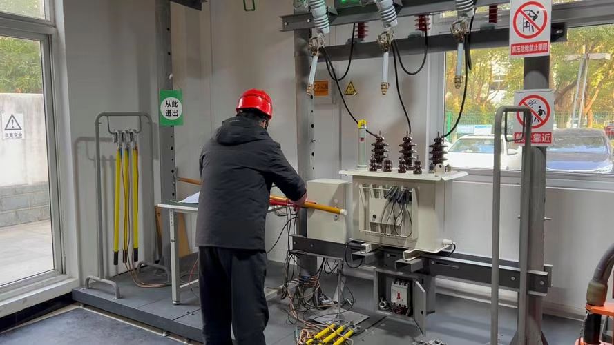
How Is the Short-Circuit Test Conducted Step-by-Step?
![]()
The short-circuit test is a critical diagnostic procedure performed on transformers to measure copper losses, determine the equivalent impedance, and validate short-circuit performance without applying full rated voltage. It is performed under controlled, low-voltage conditions to simulate full-load current. A carefully structured, step-by-step approach ensures the test is safe, accurate, and reliable.
In this article, we detail how the short-circuit test is conducted step-by-step, helping ensure precise measurement and safe operation throughout the procedure.
1. Preparation Before the Test
Actions:
- Review Transformer Specifications:
- Rated primary and secondary voltages.
- Rated full-load current.
- Rated frequency.
- Inspect Test Equipment:
- Calibrate voltmeters, ammeters, and wattmeters.
- Check the variable autotransformer (Variac) and ensure smooth operation.
- Verify the operational status of protective devices like circuit breakers or fuses.
- Confirm Safety Gear:
- Wear insulating gloves, boots, and safety glasses.
- Ensure emergency stop mechanisms are available and functional.
Goal: Ensure readiness, safety, and correct instrument settings.
2. Setting Up the Test Circuit
Actions:
- Short the High Voltage (HV) Side:
- Connect thick, low-resistance busbars or cables to short-circuit the secondary (HV) side securely.
- Connect the Low Voltage (LV) Side to Test Power:
- Attach the LV side to the low-voltage adjustable AC power supply via the Variac.
- Connect Measurement Devices:
- Connect the voltmeter across the LV terminals.
- Insert the ammeter in series with the supply line.
- Connect the wattmeter properly to measure input power.
Goal: Create a safe and stable circuit for controlled voltage application.
3. Initial System Verification
Actions:
- Ensure All Connections Are Tight:
- Loose connections can cause heating and measurement errors.
- Set the Variac Output to Zero:
- Before energizing the system, verify that no voltage is present at the input terminals.
Goal: Confirm that the setup is stable and ready for energization.
4. Energizing and Adjusting the System
Actions:
- Energize the Circuit:
- Turn on the power source while keeping the Variac at zero.
- Gradually Increase Voltage:
- Slowly adjust the Variac to increase the voltage.
- Monitor Ammeter Closely:
- Continue adjusting until the rated full-load current flows through the LV side.
- Monitor Voltmeter:
- Ensure the voltage remains much lower than the rated voltage (typically 5–10% of rated).
Goal: Achieve rated current at minimal safe voltage without overshoot.
5. Recording Measurements
Actions:
-
Record Three Critical Readings:
- Voltage (V): Low voltage applied across LV winding.
- Current (I): Full-load rated current flowing.
- Power (W): Input power, representing copper loss.
-
Stabilize Readings:
- Allow readings to stabilize for a few seconds before recording.
-
Repeat Measurements (optional):
- For enhanced accuracy, take multiple readings and average them.
Goal: Capture accurate, reliable data for subsequent analysis.
6. De-Energizing the Setup
Actions:
- Gradually Reduce Voltage to Zero:
- Lower the Variac slowly to bring voltage back to zero.
- Turn Off Power Supply:
- Switch off the source completely.
- Disconnect Test Circuit Safely:
- Remove connections systematically, ensuring no residual voltages remain.
Goal: Safely shut down the system without electrical risks.
7. Calculations and Analysis
Actions:
-
Calculate Short-Circuit Impedance (Zsc):
[Z_{sc} = \frac{V}{I}]
Where (V) is the applied voltage and (I) is the rated current. -
Determine Copper Losses:
- The wattmeter reading gives total copper (load) losses at full load.
-
Impedance Percentage:
[\%Z = \left( \frac{V}{\text{Rated Primary Voltage}} \right) \times 100]
Goal: Derive critical transformer performance parameters from the test data.
ClaimReview Fact Check
The short-circuit test procedure involves preparing the setup, gradually energizing the system, adjusting voltage to achieve rated current, recording voltage, current, and power readings, and analyzing the results for impedance and copper losses.True
Following a structured step-by-step process ensures the accuracy, reliability, and safety of the short-circuit test in transformer diagnostics.
8. Summary Table: Short-Circuit Test Procedure
| Step | Action |
|---|---|
| Preparation | Review specs, inspect equipment, ensure safety. |
| Setup | Short HV side, connect LV side to power and meters. |
| Initial Check | Verify zero voltage before energization. |
| Energization and Adjustment | Gradually increase voltage to reach rated current. |
| Measurement | Record voltage, current, and power. |
| De-Energization | Safely reduce voltage to zero and disconnect. |
| Calculation and Analysis | Derive impedance and copper losses. |
What Measurements Are Taken During the Test?
During the short-circuit test of a transformer, specific electrical measurements are taken to accurately determine key performance characteristics such as copper losses, impedance, and voltage regulation capability. The test is performed under controlled low-voltage conditions but with rated full-load current, making the measured values essential for assessing efficiency, design integrity, and fault tolerance.
In this article, we explain in detail which measurements are taken during the short-circuit test, what they signify, and how they are used for transformer analysis.
1. Voltage Across the Primary (Applied Voltage)
What Is Measured:
- The low voltage applied to the transformer's primary (usually the LV side) that is sufficient to circulate rated current.
Purpose:
- To calculate the equivalent impedance of the transformer.
- The applied voltage is typically 5–10% of the rated voltage, ensuring negligible core (iron) losses.
- Lower voltage minimizes the influence of magnetic core saturation, focusing purely on winding behavior.
Typical Instrument:
- Voltmeter (precision AC voltmeter).
2. Current Through the Primary (Rated Full-Load Current)
What Is Measured:
- The current flowing through the primary winding during the application of the short-circuit voltage.
Purpose:
- To confirm that the transformer windings are carrying rated full-load current during the test.
- The measured current ensures that copper losses are calculated under realistic operational conditions.
Typical Instrument:
- Ammeter (AC ammeter suitable for full-load current measurement).
3. Input Power (Short-Circuit Power Loss)
What Is Measured:
- The real power input to the transformer under the short-circuit condition.
Purpose:
- The input power essentially represents copper losses (I²R losses) in both the primary and secondary windings because core losses are negligible at such low voltages.
- This value is crucial for:
- Efficiency calculations.
- Thermal design verification.
- Load loss validation against manufacturer specifications.
Typical Instrument:
- Wattmeter (true RMS wattmeter for accurate low-power readings).
4. (Optional) Ambient Temperature
What Is Measured:
- The ambient temperature of the test environment during the short-circuit test.
Purpose:
- To correct copper loss readings to standard reference temperature (typically 75 °C or 85 °C, depending on standards like IEC 60076).
- Winding resistance (and thus copper loss) is temperature-dependent.
Typical Instrument:
- Digital thermometer or environmental sensor.
5. (Optional) Winding Resistance
What Is Measured:
- The DC resistance of primary and secondary windings (often measured separately before or after the short-circuit test).
Purpose:
- To independently verify calculated copper losses.
- Supports accurate modeling of the transformer’s equivalent circuit.
Typical Instrument:
- Digital micro-ohmmeter (for low-resistance measurement).
ClaimReview Fact Check
The short-circuit test measures applied voltage, current, and input power to determine transformer copper losses and impedance characteristics.True
These measurements focus on winding behavior under rated current conditions while minimizing core losses, allowing accurate assessment of transformer load performance.
Summary Table: Measurements During Short-Circuit Test
| Measurement | Purpose | Typical Instrument |
|---|---|---|
| Applied Voltage (V) | Determine equivalent impedance | Voltmeter |
| Current Through Primary (I) | Ensure rated load condition | Ammeter |
| Input Power (W) | Measure copper (load) losses | Wattmeter |
| Ambient Temperature (optional) | Correct losses to reference temperature | Thermometer |
| Winding Resistance (optional) | Validate calculated losses and resistance contribution | Micro-ohmmeter |
6. How These Measurements Are Used
| Measurement | Usage |
|---|---|
| Voltage (V) | Calculates short-circuit impedance and percentage impedance. |
| Current (I) | Confirms correct test condition (rated full-load current). |
| Power (W) | Calculates copper losses for efficiency and thermal analysis. |
| Ambient Temperature | Adjusts measured losses to standard conditions if needed. |
| Winding Resistance | Supports thermal modeling and efficiency calculations. |
The accurate capture and analysis of these parameters ensure that the transformer will operate safely and efficiently under real-world load and fault conditions.
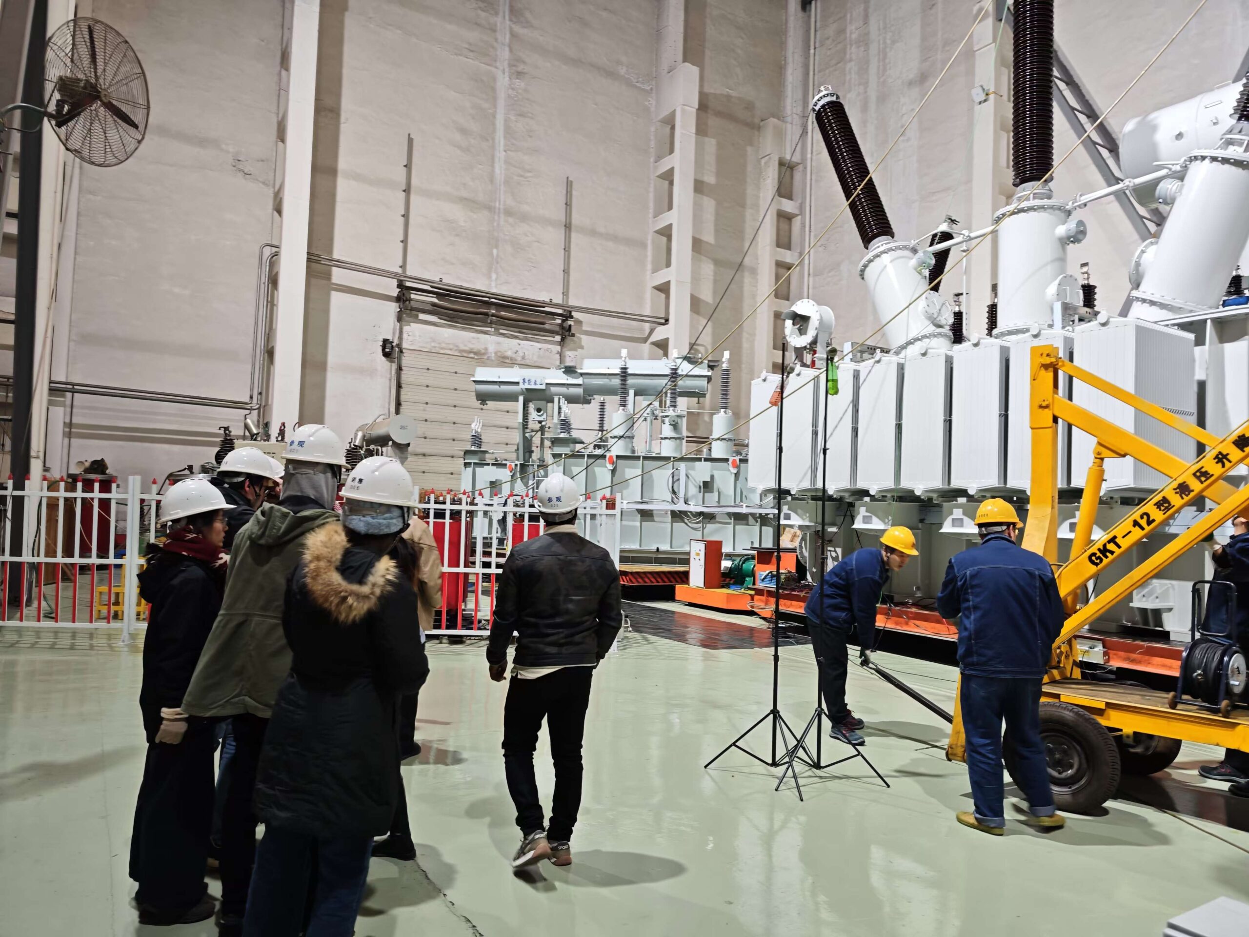
How Are Short-Circuit Test Results Analyzed?
![]()
After conducting a short-circuit test on a transformer and recording key measurements (voltage, current, power), the next essential step is to analyze the results. Proper analysis reveals critical transformer parameters such as copper losses, equivalent impedance, and voltage regulation characteristics. This evaluation helps confirm whether the transformer meets design specifications and ensures safe and efficient operation under rated load and fault conditions.
In this article, we detail how short-circuit test results are analyzed step-by-step, providing clear methods and formulas for interpreting the data accurately.
1. Verification of Test Conditions
First Step:
- Confirm that during the test, the rated full-load current was achieved.
- Ensure the applied voltage was approximately 5–10% of rated voltage to minimize core loss influence.
| Parameter | Acceptance Range |
|---|---|
| Test Voltage | 5–10% of rated primary voltage |
| Test Current | Equal to rated primary current |
Purpose:
- Validate that the conditions under which data was collected are appropriate for accurate analysis.
2. Calculation of Short-Circuit Impedance (Zₛc)
Formula:
[Z{sc} = \frac{V{sc}}{I_{rated}}]
Where:
- ( Z_{sc} ) = Short-circuit impedance (in ohms, Ω)
- ( V_{sc} ) = Applied voltage during the test (in volts, V)
- ( I_{rated} ) = Rated full-load current (in amperes, A)
Purpose:
- This impedance governs how much voltage drop and fault current the transformer will experience under load and fault conditions.
Unit:
- Ohms (Ω)
3. Expression of Impedance as a Percentage (%Zₛc)
Formula:
[\%Z{sc} = \left( \frac{V{sc}}{V_{rated}} \right) \times 100]
Where:
- ( V_{rated} ) = Rated primary voltage of the transformer.
Purpose:
- %Zₛc is used in system studies like fault analysis and coordination of protection devices.
Typical Values:
- Distribution transformers: 4–6%
- Power transformers: 8–12% (depending on design)
4. Determination of Copper Losses (Pₚc or Load Losses)
Direct Reading:
- The wattmeter reading during the short-circuit test gives the total copper loss at full load.
Purpose:
- Copper losses are critical for calculating:
- Transformer full-load efficiency.
- Thermal design for cooling systems.
- Economic operation evaluations.
Unit:
- Watts (W)
5. Correction for Temperature (If Necessary)
Since copper resistance changes with temperature:
Corrected Loss Formula:
[P{c} (T{ref}) = P{c} (T{test}) \times \left( \frac{T{ref} + 234.5}{T{test} + 234.5} \right)]
Where:
- ( T_{ref} ) = Reference temperature (typically 75 °C or 85 °C)
- ( T_{test} ) = Ambient temperature during the test
Purpose:
- Standardizes results for comparison with design values specified at standard reference temperatures.
6. Efficiency Prediction at Different Load Conditions
Once copper losses are known:
Efficiency Formula:
[\eta = \frac{Output\,Power}{Output\,Power + Copper\,Losses + Core\,Losses}]
(For efficiency at full load, considering separately measured core losses from the open-circuit test.)
Purpose:
- Analyze the economic performance of the transformer.
- Evaluate suitability for different loading scenarios.
7. Voltage Regulation Estimation
Voltage Regulation (%) can be roughly estimated using:
[\text{Voltage Regulation} \approx \%Z_{sc}]
Purpose:
- Indicates how much secondary voltage drops from no-load to full-load conditions.
- Important for assessing transformer’s performance under varying load conditions.
8. Checking Against Manufacturer Specifications
| Test Parameter | Check Against |
|---|---|
| Copper Loss (W) | Manufacturer's guaranteed losses |
| Short-Circuit Impedance (%) | Design specified value |
| Voltage Regulation (%) | Specification limit |
Purpose:
- Confirm transformer compliance with standards like IEC 60076 or IEEE C57.12.
- Verify quality and design accuracy before commissioning.
ClaimReview Fact Check
Short-circuit test analysis involves calculating copper losses, equivalent impedance, and voltage regulation from measured voltage, current, and power values.True
Measured parameters are processed through standard formulas to derive key transformer performance indicators critical for efficiency, protection, and thermal design verification.
9. Summary Table: Steps in Analyzing Short-Circuit Test Results
| Analysis Step | Formula / Action |
|---|---|
| Verify Test Conditions | Confirm rated current and low voltage |
| Calculate Short-Circuit Impedance | ( Z{sc} = V{sc} / I_{rated} ) |
| Express Impedance as Percentage | ( \%Z{sc} = (V{sc} / V_{rated}) \times 100 ) |
| Determine Copper Losses | Wattmeter direct reading (corrected if needed) |
| Correct for Temperature (if necessary) | Apply temperature correction formula |
| Predict Efficiency | Efficiency formula based on losses |
| Estimate Voltage Regulation | Approximate by %Zₛc value |
| Compare with Specifications | Confirm compliance with guaranteed values |
What Are the Safety Considerations During a Short-Circuit Test?
Short-circuit testing of transformers involves intentionally applying conditions that simulate fault-level currents at controlled voltages. Although the applied voltage is much lower than rated, the test can still produce high currents capable of causing electrical hazards, mechanical damage, or equipment failure if not properly managed. Therefore, safety is paramount during every stage of a short-circuit test to protect both personnel and equipment.
In this article, we provide a complete guide on the safety considerations necessary during a short-circuit test, ensuring that tests are conducted safely, effectively, and in compliance with best practices.
1. Pre-Test Safety Checks
| Action | Purpose |
|---|---|
| Visual inspection of equipment | Identify damaged cables, connectors, or instruments. |
| Verification of protective devices | Confirm that fuses, circuit breakers, and emergency stops are operational. |
| Calibration of instruments | Ensure voltmeters, ammeters, and wattmeters are accurate. |
| Equipment grounding | Confirm that transformer tanks, test instruments, and frames are securely grounded. |
| Clear area preparation | Ensure the test area is clean, dry, and free from conductive debris. |
Goal: Ensure all equipment is in safe operating condition before starting the test.
2. Proper Personnel Protection
| Equipment | Purpose |
|---|---|
| Insulated gloves and boots | Prevent electrical shock. |
| Safety goggles or face shields | Protect eyes against arc flashes or debris. |
| Flame-resistant clothing | Protect skin from burns in case of arcing or faults. |
| Hearing protection (earplugs/muffs) | Guard against noise from unexpected discharge sounds. |
Goal: Physically protect technicians working near the high-current circuits.
3. Secure Electrical Connections
| Safety Aspect | Action |
|---|---|
| Tight mechanical connections | Prevent sparking or heating due to loose contacts. |
| Use of appropriate cable ratings | Ensure cables can handle full-load current without overheating. |
| Avoid exposed live parts | Use insulated terminals and barriers wherever possible. |
Goal: Minimize risks of arcing, short circuits, or burns caused by loose or improper connections.
4. Controlled Voltage Application
| Safety Practice | Action |
|---|---|
| Use a variable autotransformer (Variac) | Allows gradual application of voltage. |
| Start with zero voltage | Prevent sudden surges when energizing the circuit. |
| Increase voltage slowly | Monitor current rise carefully to avoid overshooting. |
Goal: Smoothly reach rated current without causing electrical or mechanical stress.
5. Continuous Monitoring During Testing
| What to Monitor | Why It Matters |
|---|---|
| Ammeter (current) | Ensure current does not exceed rated values. |
| Voltmeter (voltage) | Confirm voltage remains within expected low range. |
| Wattmeter (power) | Detect any unusual spikes indicating circuit issues. |
| Equipment temperature | Watch for unexpected overheating or smoke. |
Goal: Quickly detect and respond to abnormalities during the test.
6. Emergency Shutdown Readiness
| Emergency Provisions | Implementation |
|---|---|
| Emergency stop button | Easily accessible to immediately cut off supply. |
| Remote control panels | Allow technicians to operate the Variac and power supply from a safe distance. |
| Automatic circuit breakers | Trip the circuit automatically if excessive current flows. |
Goal: Enable fast disconnection from power in case of a dangerous situation.
7. Post-Test Safety Procedures
| Action | Purpose |
|---|---|
| Gradual voltage reduction | Slowly lower Variac output to zero before disconnecting. |
| De-energizing the system | Switch off the main power before handling connections. |
| Discharging inductive components | Prevent stored energy from causing shocks or arcs. |
| Visual inspection after test | Check for hot spots, burns, or insulation damage. |
Goal: Ensure the system is safe to touch and inspect after testing is complete.
ClaimReview Fact Check
Strict safety measures such as grounding, protective equipment use, gradual voltage application, and continuous monitoring are essential during short-circuit testing of transformers.True
Short-circuit tests involve high currents even at low voltages, requiring rigorous safety protocols to prevent electric shock, fires, and mechanical damage.
8. Summary Table: Safety Measures in Short-Circuit Testing
| Phase | Safety Action |
|---|---|
| Pre-Test | Equipment inspection, calibration, grounding |
| Personal Protection | PPE: gloves, boots, goggles, flame-resistant clothing |
| Electrical Setup | Secure connections, appropriate cable ratings |
| Voltage Application | Gradual voltage increase using Variac |
| Continuous Monitoring | Current, voltage, power, temperature |
| Emergency Preparedness | Accessible shutdown controls, automatic breakers |
| Post-Test | De-energizing, discharging, final inspection |
Conclusion
The short-circuit test is a fundamental and highly informative procedure that ensures a transformer’s capability to handle operational and fault conditions effectively. By accurately measuring impedance and copper losses, engineers can validate the transformer’s design specifications and predict its behavior under load. Conducting the short-circuit test carefully and analyzing the results thoroughly are essential steps in ensuring transformer reliability, safety, and efficiency. As the power sector demands increasingly robust and efficient equipment, the importance of standardized testing procedures like the short-circuit test continues to grow.
FAQ
Q1: What is the purpose of the short-circuit test in transformers?
A1: The short-circuit test is performed to determine the copper losses (load losses) and the impedance voltage of a transformer under rated load conditions. It helps verify the efficiency, thermal performance, and overall quality of the transformer before operation.
Q2: How is the short-circuit test conducted on a transformer?
A2: In a short-circuit test, the secondary winding of the transformer is short-circuited, and a reduced voltage is applied to the primary winding. The applied voltage is just enough to produce rated current flow in the windings, and measurements of input voltage, current, and power are taken to calculate losses and impedance.
Q3: What equipment is needed for a short-circuit test on transformers?
A3: Essential equipment includes a variable voltage source, ammeters, voltmeters, wattmeters, and protective devices. These instruments measure the applied voltage, current, and power during the short-circuit condition.
Q4: What parameters are calculated from the short-circuit test?
A4: From the short-circuit test, the following parameters are calculated:
Copper losses (I²R losses in the windings under load)
Short-circuit impedance (which affects voltage regulation)
Voltage required to achieve full-load current (percentage impedance)
Q5: Why is the short-circuit test important for transformer performance?
A5: The short-circuit test ensures that the transformer can handle its rated load without excessive heating or voltage drops. It helps predict behavior under real operating conditions, ensures compliance with design specifications, and prevents failures caused by incorrect impedance or excessive internal losses.
References
"Understanding the Short-Circuit Test for Transformers" - https://www.transformertech.com/short-circuit-test-transformers - Transformer Tech
"How Short-Circuit Testing Ensures Transformer Reliability" - https://www.powermag.com/short-circuit-test-transformers - Power Magazine
"Short-Circuit and Impedance Testing of Transformers Explained" - https://www.electrical4u.com/transformer-short-circuit-test - Electrical4U
"Short-Circuit Testing in Power Transformers: A Practical Guide" - https://www.researchgate.net/short-circuit-test-transformers - ResearchGate
"Transformer Testing Methods: Open-Circuit and Short-Circuit Tests" - https://www.sciencedirect.com/transformer-testing-methods - ScienceDirect
"Performing a Short-Circuit Test for Transformer Health Check" - https://www.smartgridnews.com/short-circuit-testing-transformers - Smart Grid News
"Importance of Impedance Measurement in Transformers" - https://www.energycentral.com/c/ee/transformer-impedance-test - Energy Central
"Complete Guide to Transformer Short-Circuit and Load Loss Testing" - https://www.powergrid.com/transformer-short-circuit-testing - PowerGrid