In an interconnected power system, stability is essential to ensure reliable electricity supply under normal conditions and after disturbances. Transformers, though often viewed primarily as devices for voltage conversion, play a much larger role in influencing system stability. Their design, operating characteristics, and configuration can directly affect voltage regulation, power flow control, and fault recovery. Understanding how transformers impact power system stability helps engineers optimize network performance and avoid cascading failures. In this article, we will explore the critical ways transformers influence both dynamic and steady-state stability in power systems.
What is Power System Stability and Why Is It Important?
Power system stability refers to the ability of an electrical power system to maintain a state of equilibrium during and after being subjected to a disturbance. This means that even when there are sudden changes—like a generator outage, a fault on a transmission line, or a rapid load increase—the system can recover and continue operating reliably without collapsing. Stability is fundamental to ensuring continuous power delivery, protecting equipment, and preventing large-scale blackouts.
In this article, we dive into what power system stability means, why it is critically important, and how it is maintained to support safe, efficient, and resilient energy infrastructures.
1. Understanding Power System Stability
| Aspect | Description |
|---|---|
| Definition | Ability of the system to remain in a balanced operational state after being disturbed. |
| Types of disturbances | Short-circuits, sudden loss of load, generator tripping, lightning strikes, load switching, etc. |
| Stability timeframes | Can range from milliseconds (dynamic stability) to minutes (long-term stability). |
Key Concept:
- A stable power system can resist oscillations, maintain synchronization, and restore normal voltages and currents after a disturbance.
2. Main Types of Power System Stability
| Type | Focus Area |
|---|---|
| Rotor Angle Stability | Maintaining synchronism between rotating machines (generators). |
| Voltage Stability | Maintaining acceptable voltage levels across the network. |
| Frequency Stability | Keeping the system frequency (50/60 Hz) within safe limits. |
Purpose of Categorization:
- Each type addresses a different aspect of grid health and helps define specific protection and control measures.
3. Why Is Power System Stability Important?
| Reason | Impact |
|---|---|
| Prevent Blackouts | Unstable systems can lead to cascading failures and regional or national blackouts. |
| Equipment Protection | Instability can cause overvoltages, overcurrents, and mechanical damage to turbines, transformers, and substations. |
| Economic Continuity | Power disruptions cause huge financial losses in industries, businesses, and services. |
| Safety Assurance | Stable systems prevent accidents, fires, and operational hazards associated with system failures. |
| Grid Modernization | Integrating renewables, EVs, and smart grids demands even higher stability control. |
Without adequate stability, a modern interconnected power system cannot operate reliably or securely.
4. Events Threatening Power System Stability
| Event | Potential Consequence |
|---|---|
| Generator outage | Loss of generation can cause frequency drops. |
| Transmission line fault | Sudden loss of paths can overload the remaining lines. |
| Large load connection/disconnection | Causes voltage swings or frequency deviation. |
| Renewable energy fluctuations | Wind and solar variability can destabilize voltage and frequency. |
| Cyber-physical attacks | Disrupt protection systems and cause intentional instability. |
Maintaining stability requires real-time monitoring, rapid control actions, and coordinated protection systems.
5. How Is Power System Stability Maintained?
| Method | Description |
|---|---|
| Automatic Voltage Regulators (AVRs) | Maintain generator terminal voltage stability. |
| Power System Stabilizers (PSS) | Dampen oscillations in rotor angles after disturbances. |
| Load Shedding Schemes | Disconnect non-critical loads to restore balance quickly. |
| Synchronous Condensers | Provide dynamic reactive power to support voltage. |
| Fast Fault Clearing | Protective relays and breakers rapidly isolate faults. |
| Dynamic Reactive Support (FACTS Devices) | Stabilize voltage and control power flow dynamically. |
Advanced grid control technologies like HVDC links and smart inverters further enhance system resilience.
ClaimReview Fact Check
Power system stability is the ability of an electrical grid to maintain equilibrium during and after disturbances, ensuring reliable and continuous operation.True
Maintaining stability prevents cascading failures, equipment damage, service interruptions, and safety hazards, supporting reliable energy delivery to consumers.
6. Practical Examples of Power System Stability Importance
| Scenario | Result with Stability | Result without Stability |
|---|---|---|
| Lightning strike on transmission line | Fault isolated, minor disturbance, service continues. | Massive oscillations, generators lose synchronism, blackout. |
| Wind farm sudden output drop | Grid frequency managed by reserve generation. | Frequency collapse, protective shutdowns triggered. |
| Industrial load tripping | Voltage dip corrected quickly by reactive support. | Voltage collapse, extensive system outage. |
Stability mechanisms act within seconds or even milliseconds to preserve service continuity.
7. Summary Table: Key Aspects of Power System Stability
| Aspect | Summary |
|---|---|
| Definition | Ability to maintain operational equilibrium post-disturbance. |
| Types | Rotor angle, voltage, and frequency stability. |
| Importance | Prevents blackouts, protects equipment, ensures economic and safety continuity. |
| Threats | Generator loss, line faults, load fluctuations, renewables variability. |
| Stability Maintenance Methods | AVRs, PSS, FACTS devices, load shedding, fast protection. |
How Does Transformer Impedance Affect System Stability?
Transformer impedance is a critical factor influencing power system stability because it directly affects fault current levels, voltage regulation, power flow control, and system oscillations. The impedance — a combination of resistance and reactance — helps limit the magnitude of short-circuit currents, supports voltage stability, and controls load sharing among multiple generators and transformers. Therefore, correctly designed and applied transformer impedance is essential for maintaining grid stability during normal operation and under disturbance conditions.
In this article, we will explain in depth how transformer impedance affects system stability, covering technical aspects, practical implications, and design considerations.
1. What is Transformer Impedance?
| Component | Role |
|---|---|
| Resistance (R) | Represents copper losses (I²R losses) in the windings. |
| Reactance (X) | Represents the leakage flux not coupling both windings, causing voltage drops. |
| Total Impedance (Z) | Combination of resistance and reactance, usually dominated by reactance. |
Expressed as:
- Absolute value in ohms (Ω).
- Percentage impedance (%Z), which is the voltage drop caused by full-load current relative to rated voltage.
2. Impact of Transformer Impedance on Fault Currents
| Effect | Explanation |
|---|---|
| Limits Short-Circuit Current | Higher impedance reduces the fault current magnitude. |
| Protects Equipment | Lower fault currents reduce mechanical and thermal stress during faults. |
Without proper impedance:
- Extremely high fault currents can damage transformers, switchgear, and cables.
- Protective relays may fail to operate correctly, causing wider system instability.
Typical Design:
- Distribution transformers: 4–6% impedance.
- Power transformers: 8–12% impedance (depending on voltage class and system design).
3. Influence on Voltage Stability and Regulation
Transformer impedance affects:
| Condition | Impact on Stability |
|---|---|
| Normal load operation | Higher impedance causes greater voltage drop under load. |
| Disturbance (e.g., line fault) | Proper impedance helps absorb transient voltages, stabilizing the system. |
High impedance:
- Improves fault ride-through capability.
- May worsen voltage regulation if not properly compensated.
Low impedance:
- Better voltage regulation under load.
- Risks higher fault current magnitudes.
Therefore, transformer impedance must be carefully balanced between stability and voltage performance.
4. Role in Power Sharing Between Sources
When multiple transformers or generators operate in parallel:
- Impedance influences how load is shared.
- Transformers with lower impedance tend to carry more load.
- Unequal load sharing can lead to overloading of one unit while others are underloaded.
Proper impedance matching ensures:
- Stable and proportional load sharing.
- Prevention of circulating currents between transformers.
- Protection against unbalanced system stresses.
5. Dynamic Stability and Oscillation Damping
Transformer reactance affects system dynamics by:
| Effect | Impact |
|---|---|
| Damping system oscillations | Helps maintain synchronism between generators after disturbances. |
| Slowing transient swings | Reactance provides a buffer that dampens rapid frequency and angle deviations. |
In grids with high renewable penetration (which reduce system inertia), proper transformer impedance becomes even more critical to stabilize voltage and power flows dynamically.
6. Practical Design and Operational Considerations
| Aspect | Design Strategy |
|---|---|
| Short-Circuit Level Control | Choose impedance to limit fault levels within breaker interrupting ratings. |
| Voltage Drop Management | Balance impedance to prevent excessive voltage drops across feeders. |
| Parallel Operation Readiness | Ensure transformers operating in parallel have similar impedance ratings. |
| Grid Expansion Planning | Optimize transformer impedance for future system stability and load growth. |
Failure to properly consider impedance during system design can cause chronic instability, frequent protection trips, and power quality problems.
ClaimReview Fact Check
Transformer impedance affects power system stability by limiting fault currents, influencing voltage regulation, controlling power sharing, and damping system oscillations.True
Correctly designed transformer impedance helps maintain system stability during normal operations and disturbances, protecting equipment and ensuring continuous, reliable service.
7. Summary Table: How Transformer Impedance Affects Stability
| Impact Area | Role of Transformer Impedance |
|---|---|
| Fault Current Limitation | Reduces mechanical and thermal stresses. |
| Voltage Regulation | Balances load voltage drops and supports system voltage. |
| Power Sharing | Ensures stable load distribution between parallel transformers or generators. |
| Oscillation Damping | Provides dynamic system stability after disturbances. |
| Protection Coordination | Supports effective operation of relays and breakers. |
What Is the Role of Voltage Regulation by Transformers in Stability?
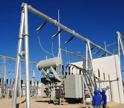
![]()
Voltage regulation by transformers plays a vital role in maintaining power system stability by ensuring that voltage levels at different points of the network stay within acceptable limits, even when load conditions vary or disturbances occur. Transformers equipped with voltage regulation capabilities—like tap changers—help manage voltage fluctuations, stabilize power flows, and prevent cascading failures that could otherwise compromise the entire grid.
In this article, we will thoroughly explain the role of voltage regulation by transformers in supporting system stability, exploring technical mechanisms, benefits, and real-world operational impacts.
1. What Is Voltage Regulation in Transformers?
| Aspect | Description |
|---|---|
| Voltage Regulation Definition | The ability of a transformer to maintain a near-constant output voltage despite changes in load. |
| Measurement | Expressed as a percentage difference between no-load and full-load voltages. |
| Enabling Mechanism | Use of tap changers—either on-load (OLTC) or off-load (NLTC)—to adjust the transformer’s turns ratio. |
Core Idea:
- Transformers help correct voltage drops or contain voltage rises, dynamically responding to system changes to keep end-user voltages stable.
2. Importance of Voltage Stability for System Operation
| Factor | Impact of Stable Voltage |
|---|---|
| Load Performance | Ensures that motors, computers, lighting, and industrial equipment operate efficiently and safely. |
| Reactive Power Balance | Helps maintain appropriate reactive power flow, critical for voltage control across the grid. |
| Protection System Coordination | Ensures that protective devices function correctly under defined voltage conditions. |
| Grid Synchronization | Supports smooth operation of interconnected generators and distributed energy resources. |
Unstable voltages can lead to equipment malfunction, increased losses, power quality issues, and ultimately widespread blackouts.
3. How Transformers Regulate Voltage
| Method | Details |
|---|---|
| On-Load Tap Changers (OLTCs) | Adjust tap settings automatically during operation without interrupting the load. |
| Off-Load Tap Changers (NLTCs) | Allow manual tap changes during maintenance or scheduled downtime. |
| Automatic Voltage Regulators (AVRs) | Monitor and control tap changes dynamically based on voltage feedback. |
Tap changers modify the effective turns ratio of the transformer, adjusting output voltage in response to:
- Load variations (increasing or decreasing demand).
- System disturbances (faults, generator trips).
- Fluctuations caused by variable renewable generation.
4. Voltage Regulation and Grid Stability During Disturbances
| Disturbance Event | Transformer Voltage Regulation Response |
|---|---|
| Sudden load increase | Tap changers adjust to raise output voltage. |
| Load shedding event | Taps adjust to lower voltage and prevent overvoltage. |
| Transmission line trip | Maintain voltage profile to avoid system separation or cascading failures. |
| Variable renewable output | Continuously balance voltage during solar and wind fluctuations. |
Result:
- Maintains voltage profiles along transmission and distribution lines.
- Prevents voltage collapse phenomena during major system disruptions.
5. Interaction with Other Stability Mechanisms
| Other Device/System | Cooperation with Transformer Regulation |
|---|---|
| Capacitor banks and reactors | Manage local reactive power to support transformer voltage control. |
| Static VAR compensators (SVCs) and STATCOMs | Provide fast-acting dynamic voltage support alongside tap-changing transformers. |
| Generator Automatic Voltage Regulators (AVRs) | Work in tandem to maintain system-wide voltage balance. |
Together, these components form an integrated voltage stability control network that protects the grid.
6. Practical Example: Substation Transformer in Action
- Scenario: During peak summer demand, air conditioning loads cause heavy voltage drops.
- Response:
- Substation transformers raise tap positions via OLTCs.
- Maintain customer voltages at acceptable levels (e.g., 400/230 V).
- Impact:
- Prevents brownouts.
- Reduces stress on industrial and residential equipment.
- Maintains regulatory voltage compliance.
Thus, tap-changing transformers act as first responders to voltage stress conditions.
ClaimReview Fact Check
Transformer voltage regulation plays a crucial role in maintaining power system stability by adjusting output voltage to balance load changes and disturbances.True
Voltage regulation prevents excessive voltage variations, stabilizes power flow, and ensures system reliability even during fluctuations in load and generation.
7. Summary Table: Transformer Voltage Regulation and Stability
| Role | Impact on Power System |
|---|---|
| Maintain Constant Output Voltage | Protects load equipment and ensures user satisfaction. |
| Stabilize Reactive Power Flow | Enhances system voltage control and reliability. |
| Support Grid Recovery from Disturbances | Prevents voltage collapse and cascading failures. |
| Enable Renewable Integration | Manages variable output conditions effectively. |
| Improve Protection and Coordination | Maintains operating conditions for relays and breakers. |
How Do Transformers Influence Fault Response and Protection Coordination?
Transformers play a critical role in fault response and protection coordination within electrical power systems. Their impedance characteristics, voltage transformation, and current-limiting capabilities directly influence how faults are detected, isolated, and cleared, protecting vital system components and maintaining overall grid stability. Correct transformer design and application ensure that protection systems operate selectively, quickly, and safely during fault conditions.
In this article, we explore in depth how transformers influence fault response and protection coordination, with technical explanations and practical system impacts.
1. Fault Behavior in Electrical Systems
| Type of Fault | Typical Effect |
|---|---|
| Short-circuit (phase-to-phase or phase-to-ground) | Extremely high currents, rapid voltage drop. |
| Open-circuit fault | Interruption in current flow, system imbalance. |
| Transformer internal faults | Winding-to-winding or winding-to-ground faults leading to severe damage if not quickly isolated. |
Transformers influence both the magnitude and dynamics of fault currents flowing through the system.
2. Transformer Impedance and Fault Current Limitation
| Transformer Characteristic | Effect on Fault Response |
|---|---|
| Higher impedance (%Z) | Limits fault current magnitude. |
| Lower impedance (%Z) | Allows higher fault currents, demanding faster protection action. |
Why Important:
- Controlled fault currents prevent mechanical damage to transformers, cables, circuit breakers, and busbars.
- Reduced fault energy simplifies protection design, allowing coordination between upstream and downstream devices.
3. Transformer Influence on Protection Device Selection
| Protection Device | Transformer Impact |
|---|---|
| Circuit breakers | Must be rated based on maximum possible fault current after considering transformer impedance. |
| Relays (overcurrent, differential, distance) | Settings are based on transformer voltage and current transformation ratios. |
| Fuses | Size and speed must match downstream transformer behavior. |
Key Considerations:
- Transformers define fault levels at secondary systems.
- They set coordination limits between primary and backup protection devices.
4. Differential Protection and Transformer Zones
Transformers often have dedicated differential protection to detect internal faults:
| Protection Principle | Action |
|---|---|
| Differential protection | Measures difference between incoming and outgoing currents; triggers instant trip if imbalance exceeds threshold. |
Benefit:
- Highly sensitive to internal faults (e.g., winding short-circuits).
- Minimizes damage by isolating faulty transformers in milliseconds.
Special Challenge:
- Transformer vector groups (e.g., YΔ, ΔY) introduce phase shifts, requiring special CT (current transformer) compensation for accurate differential relay operation.
5. Transformer Role in Protection Coordination Schemes
| Coordination Aspect | Transformer Influence |
|---|---|
| Selectivity | Ensures only faulty parts are disconnected, not entire system sections. |
| Sensitivity | Enables relays to detect low-magnitude faults without nuisance trips. |
| Speed | Ensures rapid fault clearing to protect equipment and maintain stability. |
Example:
- A fault near a distribution transformer should trigger the closest protection device (e.g., secondary breaker) first, not trip the upstream feeder breaker unnecessarily.
6. Specific Transformer Features Supporting Protection
| Feature | Impact on Fault Response |
|---|---|
| Tap changers with automatic adjustment | Maintain correct voltage, preventing undervoltage and relay misoperation during fluctuating loads. |
| Grounded winding configurations (e.g., Y grounded) | Enable easy detection and clearing of single-line-to-ground faults. |
| High-voltage bushings with built-in sensors | Allow condition monitoring to detect partial discharges early. |
These features enhance system protection reliability and simplify fault diagnosis.
7. Real-World Example: Transformer Fault Coordination Scenario
Scenario:
- A phase-to-ground fault occurs on the LV side of a distribution transformer.
Transformer Influence:
- The transformer’s impedance limits the peak fault current.
- LV-side protection devices (like breakers or fuses) operate first.
- HV protection (primary feeder breaker) remains closed unless fault escalates.
Outcome:
- Local fault isolation, minimal system disturbance, no unnecessary upstream trips.
Thus, transformer characteristics are the first line of defense in fault localization and containment.
ClaimReview Fact Check
Transformers influence fault response and protection coordination by limiting fault currents, enabling selective protection operation, and supporting quick, localized fault clearing.True
Transformer impedance, voltage transformation, and configuration directly affect how faults propagate and how protective relays and breakers respond, maintaining system integrity and minimizing service disruption.
8. Summary Table: Transformer Roles in Fault Response and Protection
| Aspect | Transformer Influence |
|---|---|
| Fault Current Limitation | Controls magnitude of fault energy to safe levels. |
| Protection Device Calibration | Defines relay and breaker settings based on transformed voltages/currents. |
| Differential Protection | Provides fast detection of internal faults. |
| Protection Coordination | Ensures correct, selective isolation of faults. |
| System Stability Support | Helps maintain operational integrity during faults. |
How Does the Transformer Connection Type Impact Power System Stability?
Transformer connection types—such as Delta (Δ), Wye (Y), or combinations like Delta-Wye (Δ/Y) and Wye-Delta (Y/Δ)—have a major impact on power system stability. The choice of connection affects fault current behavior, voltage balance, neutral grounding, and the ability to ride through disturbances. Each configuration supports stability differently, influencing how effectively the system can maintain continuous, balanced, and safe operation under normal and faulted conditions.
In this article, we explore in depth how transformer connection types impact power system stability, highlighting technical effects, operational benefits, and design considerations.
1. Overview of Common Transformer Connection Types
| Connection Type | Description |
|---|---|
| Delta-Delta (Δ-Δ) | Both primary and secondary windings are connected in delta. |
| Delta-Wye (Δ-Y) | Primary in delta, secondary in wye (star). Common in transmission and distribution. |
| Wye-Delta (Y-Δ) | Primary in wye, secondary in delta. Useful for industrial applications. |
| Wye-Wye (Y-Y) | Both sides connected in wye. Needs careful grounding to ensure stability. |
Each configuration offers different advantages for system design, fault handling, and voltage management.
2. Fault Current Management and Stability
| Connection Type | Fault Behavior Impact |
|---|---|
| Delta-connected winding | Provides a closed path for circulating currents during unbalanced faults, helping stabilize voltages. |
| Wye-grounded connection | Offers a clear path for ground fault current detection and protection coordination. |
| Ungrounded Wye | Makes ground fault detection more difficult; system can operate during single-line-to-ground faults but with potential overvoltages. |
Importance:
- Delta connections stabilize phase voltages during unbalanced faults.
- Wye-grounded connections facilitate rapid fault detection and isolation, improving post-fault stability.
3. Neutral Point Availability and Grounding
Wye-connected transformers:
- Provide a neutral point for grounding.
- Allow the system to maintain stable phase voltages even during asymmetrical faults.
Delta-connected transformers:
- Do not inherently provide a neutral.
- Often paired with grounding transformers (zig-zag or grounded-wye auxiliary transformers) when a neutral point is needed.
Impact on Stability:
- Proper grounding stabilizes system voltages under fault conditions.
- Reduces temporary overvoltages after clearing single-line-to-ground faults.
- Improves protection system reliability and coordination.
4. Voltage Transformation and Load Balancing
| Connection Impact | Operational Stability Effect |
|---|---|
| Δ-Y configuration | Steps up or down voltage efficiently; isolates harmonics. |
| Δ-Δ configuration | Suitable for heavily unbalanced industrial loads. |
| Y-Y configuration | Simpler for direct phase-to-phase voltage transformation, but needs solid grounding for stability. |
Benefit:
- Proper voltage transformation across connections prevents voltage instability during load variations and transients.
- Improves system power factor and reduces harmonic distortions, helping maintain steady-state stability.
5. Harmonic Mitigation and Dynamic Stability
Delta-connected transformers:
- Trap third-harmonic and triplen (3rd, 9th, etc.) harmonics internally.
- Prevent harmonic propagation into the wider grid.
Wye-connected transformers:
- Without harmonic suppression, can allow harmonics into the network if not managed.
Impact:
- Reduces voltage waveform distortion.
- Improves dynamic system response after disturbances.
Thus, using a delta winding on at least one side enhances harmonic control and system stability.
6. Parallel Operation and System Strength
| Requirement | Effect on Stability |
|---|---|
| Identical connection types | Needed for parallel operation without circulating currents. |
| Matching phase shifts | Prevents inadvertent unbalance and instability. |
Example:
- Δ-Y transformers introduce a 30° phase shift between primary and secondary voltages.
- If mismatched with other transformers, can cause circulating currents, loss of synchronism, and protection maloperation.
Proper transformer phasing ensures coordinated, stable operation of multi-source and multi-load grids.
7. Practical Examples of Connection Type Impact
| Situation | Result with Good Connection Choice | Result with Poor Connection Choice |
|---|---|---|
| Transmission Substation (Δ-Y) | Stable voltage step-up, easy ground fault detection. | Difficult fault isolation, increased downtime. |
| Industrial Plant with Heavy Motor Loads (Δ-Δ) | Balanced operation under asymmetrical loads. | Unstable voltages, overheating of equipment. |
| Rural Distribution with Unbalanced Loads (Y-Y with neutral grounding) | Maintains voltage during uneven loading. | Flickering lights, unstable motor performance. |
ClaimReview Fact Check
Transformer connection type impacts power system stability by affecting fault behavior, grounding, voltage balance, harmonic suppression, and parallel operation capabilities.True
Proper transformer connection configurations help manage faults, ensure voltage stability, suppress harmonics, and allow coordinated protection system operation, supporting grid resilience and reliability.
8. Summary Table: Connection Type Effects on System Stability
| Connection Type | Stability Effect |
|---|---|
| Delta-Delta (Δ-Δ) | Stabilizes unbalanced loads; no neutral available without auxiliary grounding. |
| Delta-Wye (Δ-Y) | Provides neutral for grounding; manages harmonics; ideal for transmission step-up. |
| Wye-Delta (Y-Δ) | Isolates phase shift effects; handles fault currents effectively with grounded Y. |
| Wye-Wye (Y-Y) | Requires good grounding; prone to overvoltages if ungrounded. |
What Future Technologies in Transformers Support Enhanced System Stability?
Future transformer technologies are evolving rapidly to meet the growing demands of system stability, grid resilience, and renewable energy integration. Innovations like solid-state transformers, smart monitoring systems, digitized controls, and adaptive designs aim to make transformers more dynamic, intelligent, and responsive. These technologies will empower the next-generation power grid to maintain voltage stability, frequency regulation, and fault resilience even under highly variable and complex conditions.
In this article, we explore the future technologies in transformers that support enhanced system stability, their mechanisms, and their transformative impact on modern power systems.
1. Solid-State Transformers (SSTs)
| Feature | Impact on Stability |
|---|---|
| Power electronic-based design | Provides fast voltage regulation and dynamic load control. |
| Multi-port capabilities | Connects AC, DC, and storage systems seamlessly. |
| High-frequency operation | Reduces size, enhances power density and dynamic response. |
Benefits:
- Enables rapid adaptation to grid disturbances.
- Supports integration of distributed generation and microgrids.
- Allows flexible energy routing to maintain local and system-wide balance.
Impact:
- SSTs actively stabilize voltage and frequency under fluctuating load and generation conditions.
2. Smart Transformers with Embedded Monitoring
Smart transformers incorporate:
| Embedded Technology | Purpose |
|---|---|
| Temperature sensors | Monitor internal heating and thermal stability. |
| Voltage and current sensors | Track real-time load and operating conditions. |
| Digital protection relays | Enable faster and more selective fault isolation. |
| Fiber-optic monitoring | Detect insulation aging and hotspots early. |
Benefits:
- Proactive identification of instability risks.
- Autonomous adjustment of settings for load balancing and voltage regulation.
- Predictive maintenance improves transformer health and reduces unexpected outages.
3. Digital Twin Technology
Digital twins are virtual replicas of physical transformers, continuously updated using live data.
| Function | Stability Support |
|---|---|
| Real-time simulation | Predicts behavior under various disturbances and operational changes. |
| Advanced analytics | Identifies potential failures before they impact stability. |
Impact:
- Allows grid operators to simulate scenarios and optimize transformer control settings dynamically.
- Enhances decision-making during fault recovery and load management.
4. Self-Healing Transformer Materials
Emerging material science innovations include:
| Material Technology | Purpose |
|---|---|
| Self-healing dielectric insulation | Repairs minor cracks and breakdowns automatically. |
| Nano-enhanced oils and solids | Improve thermal conductivity and breakdown strength. |
Impact:
- Enhances long-term mechanical and dielectric stability.
- Reduces failure rates during overloads and transients.
Self-healing transformers would improve resilience, significantly reducing the risk of instability from equipment failures.
5. Wide-Bandgap Semiconductors for Transformer Applications
Materials like Silicon Carbide (SiC) and Gallium Nitride (GaN) in power electronics allow:
| Advantage | Effect on Transformers |
|---|---|
| High efficiency at higher frequencies | Enables smaller, faster-reacting transformers. |
| Lower switching losses | Supports dynamic load balancing with minimal energy loss. |
Impact:
- Ultra-fast response to system disturbances.
- Supports compact designs for decentralized grids and renewable integration nodes.
6. Advanced Cooling Techniques
Future transformers are adopting:
| Cooling Innovation | Stability Benefit |
|---|---|
| Forced liquid and air hybrid cooling | Rapidly removes heat during high-load or fault conditions. |
| Nano-fluid cooling technologies | Increase heat dissipation rates significantly. |
Impact:
- Enables higher power handling without overheating.
- Supports thermal stability during transient system events.
Cooling advancements ensure that transformers maintain operational integrity even during heavy fault currents or sudden load surges.
7. Flexible Transformer Architectures for Dynamic Grids
| Concept | Stability Contribution |
|---|---|
| Modular transformers | Adapt capacity dynamically to load growth or reconfiguration. |
| Plug-and-play interfaces | Allow quick replacement and addition of transformers in the field. |
Impact:
- Makes grids more adaptable and resilient to failures and changing power flows.
- Supports islanding strategies in microgrids during large-scale system disturbances.
ClaimReview Fact Check
Future transformer technologies like solid-state transformers, smart monitoring, digital twins, and self-healing materials enhance power system stability by improving fault response, voltage regulation, and predictive control.True
Advanced transformer designs integrate sensing, dynamic control, simulation, and material innovations, empowering grids to maintain stability under highly variable and decentralized conditions.
8. Summary Table: Future Transformer Technologies Supporting Stability
| Technology | Stability Enhancement |
|---|---|
| Solid-State Transformers (SSTs) | Fast voltage/frequency control and multi-port energy routing. |
| Smart Transformers | Real-time health monitoring and self-adjustment. |
| Digital Twin Simulation | Predictive fault and instability modeling. |
| Self-Healing Materials | Automatic insulation repair during stress. |
| Wide-Bandgap Semiconductors | High-speed, efficient transformer operations. |
| Advanced Cooling Solutions | Thermal management during load surges. |
| Modular Transformer Designs | Flexible scaling and rapid fault recovery. |
Conclusion
Transformers are more than just passive electrical devices — they actively shape the behavior and stability of entire power systems. Through their impedance characteristics, voltage regulation capabilities, and connection configurations, transformers influence how a system reacts to load changes, faults, and recovery events. As power grids evolve toward greater complexity and the integration of renewable energy, advanced transformer technologies will play an even more critical role in enhancing system stability, reliability, and efficiency. Understanding their influence is key to designing smarter and more resilient power networks for the future.
FAQ
Q1: How do transformers contribute to power system stability?
A1: Transformers contribute to power system stability by regulating voltage levels, balancing load distribution, and facilitating efficient energy transfer across the grid. They ensure that power is transmitted safely and reliably from generation sources to consumers, helping maintain consistent and stable electrical system operation.
Q2: How does voltage regulation by transformers impact system stability?
A2: Voltage regulation by transformers ensures that voltage levels remain within safe limits throughout the power network. By stepping up or stepping down voltages appropriately, transformers prevent voltage sags, spikes, and instability, which could otherwise cause equipment malfunction or system-wide blackouts.
Q3: What is the role of transformer impedance in system stability?
A3: Transformer impedance affects how much voltage drops under load conditions and influences short-circuit currents during faults. Proper impedance design helps limit fault currents and control voltage fluctuations, contributing to greater system resilience and minimizing the risk of widespread outages.
Q4: How do transformers assist in fault management and protection?
A4: During faults (like short circuits), transformers help isolate problem areas by limiting fault current levels and enabling protective devices (like circuit breakers) to operate effectively. This containment prevents fault propagation, helping stabilize the overall power system and restore normal operations quickly.
Q5: Why is transformer load balancing important for power system stability?
A5: Transformer load balancing ensures that no part of the system is overloaded, which could lead to overheating, inefficiencies, or failures. Properly sized and configured transformers distribute load evenly across phases and circuits, promoting a stable, efficient, and reliable power supply throughout the grid.
References
"The Role of Transformers in Power System Stability" - https://www.transformertech.com/transformers-power-stability - Transformer Tech
"Understanding How Transformers Affect Grid Stability" - https://www.powermag.com/transformer-impact-on-grid-stability - Power Magazine
"Transformer Influence on Electrical System Reliability" - https://www.electrical4u.com/transformer-system-stability - Electrical4U
"Voltage Regulation and Transformer Stability in Power Systems" - https://www.researchgate.net/transformer-voltage-regulation-stability - ResearchGate
"Managing Power System Stability with Transformers" - https://www.sciencedirect.com/transformer-system-stability - ScienceDirect
"Transformers and Their Role in Fault Management" - https://www.smartgridnews.com/transformers-fault-management - Smart Grid News
"How Transformers Improve Power Grid Resilience" - https://www.energycentral.com/c/ee/transformers-power-grid-resilience - Energy Central
"Enhancing Power System Stability Using Transformer Technology" - https://www.powergrid.com/transformer-power-system-stability - PowerGrid