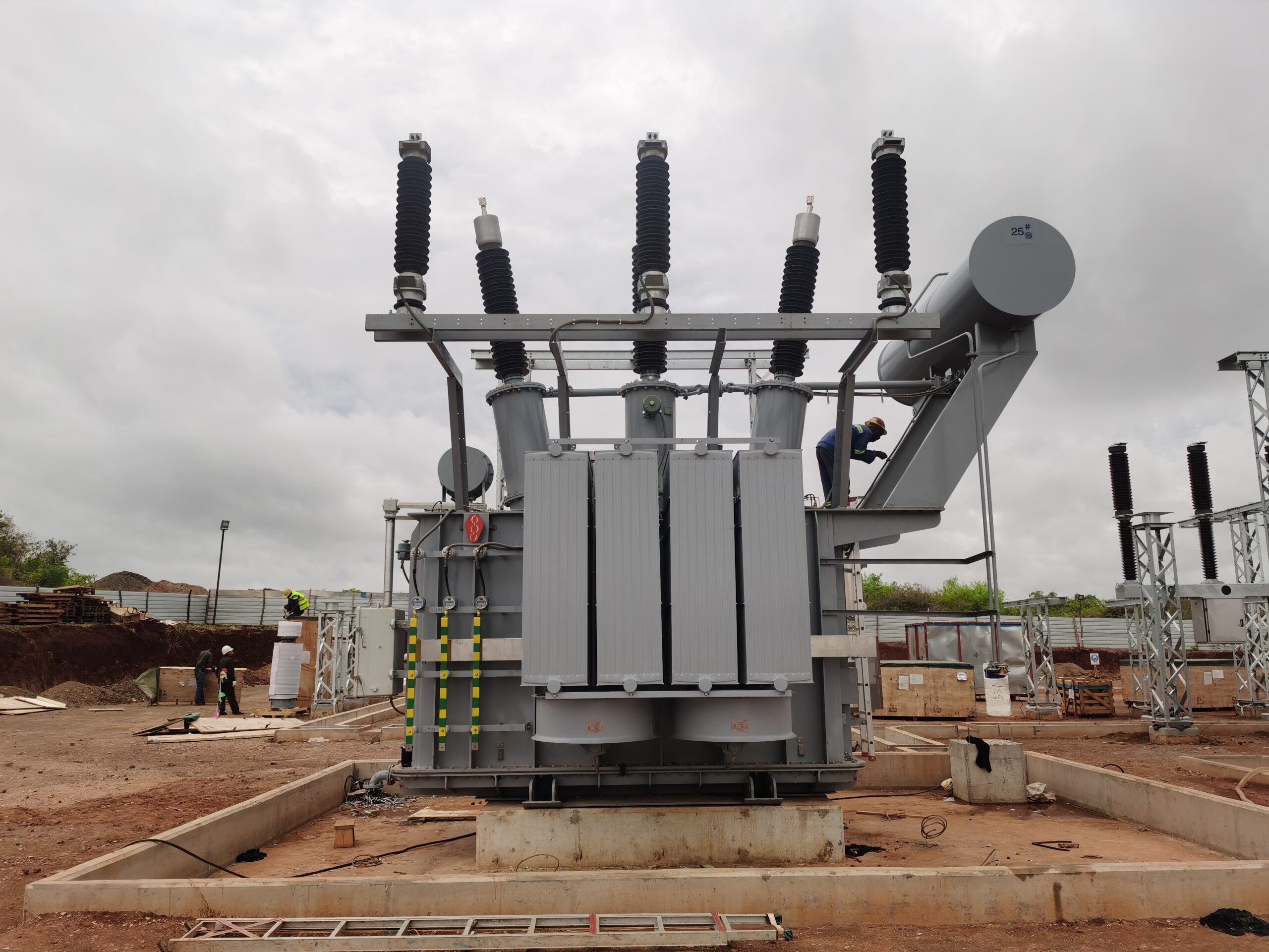
Electrical protection in transformers is essential to safeguard both the transformer and the broader power system from faults, overloads, and abnormal operating conditions. Transformers are critical assets in energy infrastructure, and any failure can lead to costly outages, equipment damage, or even safety hazards. To mitigate these risks, transformers are equipped with a range of protection systems that detect electrical faults and trigger automatic responses. This article explores what electrical protection means in the context of transformers, the types of protection used, and how these systems function to ensure operational safety and reliability.
What is Electrical Protection in Transformers?
Electrical protection in transformers refers to the comprehensive system of protective devices, control logic, and monitoring techniques designed to detect abnormal electrical conditions and automatically isolate faults to prevent damage to the transformer and the surrounding power network. This protection is essential to ensure operational reliability, equipment longevity, grid stability, and safety for personnel and infrastructure. A transformer without proper electrical protection is vulnerable to failures from internal insulation breakdown, external short circuits, overloading, or surges—each of which can result in extensive damage or even transformer explosion.
This article explores the components, mechanisms, and strategies used in transformer electrical protection and explains how they work together to prevent failures and prolong transformer life.
1. Why Electrical Protection Is Critical in Transformers
Electrical protection is essential because transformers are exposed to multiple electrical hazards that, if unaddressed, can lead to severe operational and safety consequences.
| Hazard Type | Example Event | Possible Damage |
|---|---|---|
| Internal faults | Winding-to-winding short circuit | Severe arc flash, insulation burn-through |
| Overloading | Prolonged high current load | Insulation aging, thermal breakdown |
| External short circuits | Fault on connected feeders | Magnetic forces deforming windings |
| Surge voltages | Lightning or switching surges | Bushing flashover, dielectric puncture |
| Overheating | Fan failure or high ambient temperatures | Paper degradation, eventual failure |
Without protection systems, these faults can escalate within milliseconds, leading to transformer destruction, grid collapse, or fire hazards.
2. Core Components of Electrical Protection in Transformers
| Protection Device | Function |
|---|---|
| Differential Relay (87T) | Detects internal phase or inter-turn faults |
| Overcurrent Relay (50/51) | Protects against sustained overloading or external faults |
| Ground Fault Relay (50N/51N) | Detects current leakage to ground (insulation failure) |
| Buchholz Relay | Detects gas formation and internal arc faults in oil-filled units |
| Surge Arresters | Divert overvoltages from lightning or switching events |
| Temperature Relays | Trips the transformer during overheating conditions |
| Pressure Relief Devices | Releases excess pressure due to internal arc or oil vaporization |
3. Differential Protection (87T) – Primary Internal Fault Protection
Principle: This method works on the concept of Kirchhoff’s Current Law:
The current entering a healthy transformer should equal the current leaving it (after accounting for the turns ratio).
| Component | Role |
|---|---|
| Current transformers (CTs) | Measure current on both HV and LV sides |
| Differential relay | Trips the breaker if a current imbalance is detected |
Key Advantage:
Extremely fast response time (20–50 ms), ideal for limiting damage in internal winding faults.
Harmonic restraint is included to prevent false tripping during magnetizing inrush.
4. Overcurrent and Earth Fault Protection
| Protection Type | Purpose |
|---|---|
| Instantaneous Overcurrent (50) | Trips on very high fault current instantly |
| Time-Delayed Overcurrent (51) | Trips after a set time during overload |
| Ground Fault (50N/51N) | Detects unbalanced current from insulation faults |
Coordination is key: These relays must coordinate with feeder breakers to avoid nuisance tripping.
5. Buchholz Relay – Exclusive to Oil-Immersed Transformers
| Detection Trigger | Relay Response |
|---|---|
| Gas accumulation (slow fault) | Triggers alarm |
| Oil surge (major internal arc) | Trips transformer via relay contacts |
Why it's unique: It detects slow-developing faults like insulation breakdown or gas from arcing, which aren't always captured by electrical relays.
6. Surge and Lightning Protection
| Protection Device | Function |
|---|---|
| Surge Arresters | Clamp voltage spikes and redirect surge energy to ground |
| Capacitor Voltage Dividers | Help dampen switching overvoltages |
Important Fact: Surge arresters are mounted near bushings and cable terminations, providing first-line defense against external transients.
7. Thermal Protection and Monitoring
| Method | Use |
|---|---|
| Temperature relays | Monitor top oil and winding hot-spot temperatures |
| Cooling system triggers | Activate fans or pumps at preset thresholds |
| Trip functions | Disconnect transformer if critical temperature is exceeded |
Standard Setting Examples:
- Oil temperature alarm: 90°C
- Oil temperature trip: 105°C
- Winding hot-spot trip: ~120°C
Key Insight: Thermal protection is directly tied to insulation aging and electrical life.
8. Pressure and Explosion Protection
| Device | Function |
|---|---|
| Pressure Relief Valve | Prevents tank rupture during gas pressure rise |
| Explosion Vent | Last-resort safety measure for violent internal faults |
These devices are required in sealed oil-filled transformers to prevent tank explosions from trapped gases during arcing faults.
ClaimReview Fact Check**
Electrical protection in transformers uses devices like relays, sensors, and surge arresters to detect and isolate faults, preserving transformer safety and functionality.True
These protection systems are essential for detecting internal faults, overvoltages, overcurrents, and overheating, allowing fast disconnection before equipment damage or failure occurs.
9. Summary Table: Electrical Protection in Transformers
| Protection Scheme | Targeted Fault or Risk | Primary Devices Used |
|---|---|---|
| Internal winding fault | Short circuit, inter-turn fault | Differential relay (87T) |
| External fault or overload | Overcurrent or short circuit | Overcurrent relay (50/51) |
| Earth fault | Ground leakage or insulation failure | Ground fault relay (50N/51N) |
| Gas and arc detection | Internal arcing and gas generation | Buchholz relay |
| Lightning/switching surge | External voltage spikes | Surge arresters |
| Overtemperature | Overloading, cooling failure | Thermal sensors and relays |
| Overpressure | Arc-induced gas buildup | Pressure relief valves |
What Types of Faults Can Occur in Transformers?
Faults in transformers are abnormal conditions that disrupt normal operation and can lead to equipment damage, power outages, or even explosions if not promptly detected and addressed. These faults can be electrical, mechanical, thermal, or environmental in nature, occurring either internally (within the transformer tank or windings) or externally (in the connected power system). Understanding the types of faults that can occur is essential for protection system design, predictive maintenance, and life extension planning.
This article identifies and explains the main types of transformer faults, their causes, consequences, and how they are typically detected and mitigated.
1. Internal Electrical Faults
These faults originate within the transformer's core, windings, or insulation system and are usually the most dangerous due to high energy concentration and potential for total transformer failure.
| Fault Type | Description | Potential Causes |
|---|---|---|
| Winding short circuit | Short between turns of the same winding or between different windings | Insulation breakdown due to aging, overheating, or mechanical movement |
| Inter-turn fault | Fault between adjacent turns in a coil | Localized insulation failure |
| Phase-to-phase fault | Contact between two phases | Dielectric failure, bushing flashover |
| Phase-to-ground fault | Conductor touches transformer core or tank | Moisture ingress, insulation puncture |
Detection Tools:
- Differential protection relays
- Dissolved Gas Analysis (DGA)
- Buchholz relay for oil-filled units
2. External Electrical Faults
These faults occur in the network connected to the transformer, such as incoming or outgoing feeders, but can stress the transformer if not isolated quickly.
| Fault Type | Description | Potential Causes |
|---|---|---|
| Short circuit on load side | Large current drawn due to downstream fault | Equipment failure, cable faults |
| Overvoltage or surge | Excessive voltage due to lightning or switching | Lightning strikes, capacitor bank switching |
| Unbalanced loading | Asymmetrical currents in three-phase systems | Unequal load distribution |
Protection Devices:
- Overcurrent relays
- Surge arresters
- Voltage regulation systems
3. Thermal Faults
These faults occur when the transformer exceeds its design temperature, leading to insulation aging and eventual failure.
| Fault Type | Description | Potential Causes |
|---|---|---|
| Overheating of windings | Hot spots due to overloading or blocked cooling | Excessive load, radiator clogging, fan failure |
| Oil degradation | Loss of cooling and dielectric properties | Long service life, poor maintenance |
Detection Tools:
- Temperature sensors (hot-spot and oil)
- Thermal imaging and infrared scans
- Oil analysis for Total Acid Number (TAN) and interfacial tension
4. Mechanical Faults
Mechanical stress can cause damage to windings, leads, and structural supports, especially during faults or transportation.
| Fault Type | Description | Potential Causes |
|---|---|---|
| Winding displacement | Movement of coils within the core window | Short circuit forces, inadequate bracing |
| Bushing failure | Cracks or internal breakdown | Manufacturing defect, contamination |
| Tap changer failure | Fault in voltage regulation mechanism | Excessive operation, carbon tracking |
Detection Tools:
- Frequency Response Analysis (FRA)
- Mechanical inspection
- Partial Discharge (PD) testing
5. Dielectric Faults
These involve the breakdown of insulating materials due to electrical or thermal overstress, often resulting in flashovers or arcing.
| Fault Type | Description | Potential Causes |
|---|---|---|
| Insulation flashover | Breakdown across bushing or windings | High humidity, aged insulation |
| Partial discharge | Localized electrical activity in voids or cracks | Thermal cycling, contamination, paper aging |
Detection Tools:
- Partial discharge detectors
- DGA (presence of acetylene and hydrogen)
- Insulation resistance and tan delta tests
6. Oil and Gas Faults
Oil in transformers is essential for cooling and insulation. Faults here can signal or cause serious problems.
| Fault Type | Description | Potential Causes |
|---|---|---|
| Gas formation | Combustible gases in oil from insulation breakdown | Arcing, overheating, insulation degradation |
| Oil leaks | External loss of insulating oil | Corrosion, poor gasket seals |
| Sludge accumulation | Thick byproduct of oil oxidation | High acidity, long-term thermal stress |
Detection Tools:
- Buchholz relay
- Oil DGA and furan analysis
- Oil sampling and laboratory tests
ClaimReview Fact Check
Transformers can experience internal, external, thermal, mechanical, dielectric, and oil-related faults, each requiring specific detection and protection strategies.True
These faults result from insulation breakdown, overloads, oil degradation, mechanical displacement, or external electrical stress, and identifying them early ensures transformer reliability and safety.
7. Summary Table: Types of Transformer Faults
| Fault Category | Common Faults | Typical Detection Methods |
|---|---|---|
| Internal Electrical | Inter-turn short, phase-to-ground fault | Differential relays, DGA, Buchholz relay |
| External Electrical | Load-side short, surge, unbalance | Overcurrent protection, surge arresters |
| Thermal | Hot-spot overheating, oil breakdown | Thermal sensors, oil testing |
| Mechanical | Winding movement, tap changer failure | FRA, physical inspection |
| Dielectric | Flashover, partial discharge | PD detectors, tan delta test, DGA |
| Oil and Gas | Gas generation, sludge, leaks | DGA, Buchholz, oil quality analysis |
What Are the Main Protection Devices Used in Transformers?
Transformers are vital components in electrical power systems, responsible for transferring energy between circuits through electromagnetic induction. However, like all critical equipment, they are susceptible to various faults—overheating, overcurrent, insulation failure, oil leakage, and internal arcing. A lack of proper protection can result in severe damage, service interruption, and even catastrophic failure. Fortunately, a range of transformer protection devices exists to mitigate these risks. Understanding these devices—and their roles—is essential for system reliability, safety, and longevity.
The main protection devices used in transformers include Buchholz relays, differential protection relays, pressure relief devices, temperature sensors, oil level indicators, surge arresters, and circuit breakers. Each device serves a specific function, such as detecting internal faults, overcurrent, overpressure, and temperature rise to initiate alarms or disconnect the transformer from the power system before damage occurs.
Whether you're designing a power grid, managing substation operations, or selecting components for a commercial building, recognizing and implementing the correct transformer protection devices ensures operational safety and prevents costly failures. Keep reading for an in-depth breakdown of each device and its role in modern transformer protection schemes.
Buchholz relays are used only in air-cooled transformers.False
Buchholz relays are gas-actuated protection devices used specifically in oil-immersed transformers to detect internal faults and gas accumulation.
Transformer protection relays can detect both internal and external faults.True
Relays such as differential and overcurrent relays can be configured to detect faults occurring both inside and outside the transformer boundaries.
Buchholz Relay – The Sentinel of Internal Faults
A Buchholz relay is a mechanical gas-actuated protection device used in oil-immersed transformers, installed between the main tank and the conservator. It detects the formation of gas due to insulation breakdown or arcing and responds to oil flow caused by severe faults.
Technical Operation:
| Fault Type | Buchholz Relay Action | Time Response | Common Trigger |
|---|---|---|---|
| Minor internal fault | Gas accumulation, alarm | Slow | Insulation degradation |
| Major internal fault | High oil flow, tripping relay | Fast (<100 ms) | Short circuit or arc |
Case Study: In a 20MVA oil-immersed transformer at a thermal power plant, a Buchholz relay triggered a shutdown within seconds of a sudden internal arc, preventing fire and total unit loss.
H3: Differential Protection Relay – The Fault Current Watchdog
Differential protection is one of the most sensitive and accurate methods of internal transformer fault detection. It compares the current entering and leaving the transformer under normal operation. Any mismatch indicates a fault within the transformer.
Sample Calculation of Protection Logic:
Let ( I{primary} ) = 500 A, ( I{secondary} ) (converted to primary side) = 485 A.
Differential current ( Id = |I{primary} - I_{secondary}| = 15 A )
If relay setting is 10 A → Trip signal is generated
Relay Coordination Table:
| Transformer Rating | Relay Type | Setting Range (A) | Trip Time (ms) |
|---|---|---|---|
| ≤10 MVA | Static Differential | 5–10 | 40–100 |
| >10 MVA | Numerical Differential | 10–20 | 30–80 |
Temperature and Thermal Protection – Overheating Preventers
Oil-immersed and dry-type transformers both rely heavily on thermal monitoring. Devices include RTDs (Resistance Temperature Detectors), thermocouples, and thermostats that trigger alarms or fans when limits are exceeded.
Temperature Control Flow:
- RTDs measure winding temperature.
- Data sent to relay/controller.
- Controller activates cooling fan or trips system if temperature > setpoint.
Chart: Temperature Thresholds
| Device Type | Alarm Temp (°C) | Trip Temp (°C) | Reset Temp (°C) |
|---|---|---|---|
| Oil-Immersed | 90 | 105 | 85 |
| Dry-Type | 120 | 140 | 100 |
Pressure Relief Devices – Preventing Explosions
Transformers with sealed tanks need a way to relieve pressure from internal arcing or oil expansion. Pressure relief devices (PRD) or explosion vents open automatically when pressure exceeds safety limits.
Design Insight: These devices include spring-loaded diaphragms that rupture under excessive pressure, venting gases safely without compromising insulation.
Example Specs:
| Transformer Size | PRD Type | Activation Pressure (bar) |
|---|---|---|
| ≤5 MVA | Basic Diaphragm | 0.4–0.8 |
| >5 MVA | Spring-loaded PRD | 0.6–1.2 |
Surge Arresters – Shielding from Voltage Spikes
To guard against transient voltage surges caused by lightning or switching, metal-oxide surge arresters (MOSAs) are installed at transformer terminals.
Chart: Surge Arrester Characteristics
| System Voltage (kV) | Arrester Rated Voltage (kV) | Discharge Voltage (kV) |
|---|---|---|
| 11 | 12 | 30 |
| 33 | 36 | 85 |
| 132 | 144 | 340 |
Real-world Use: In 2022, a wind farm in Germany prevented a cascading failure due to a lightning strike thanks to well-rated MOSAs protecting 50 MVA transformers.
Circuit Breakers and Fuses – Rapid Isolation Mechanisms
While relays detect faults, circuit breakers and HV fuses are the physical actuators that isolate the transformer from the grid or load.
Table: Typical CB Settings for Transformer Protection
| Transformer Capacity | Breaker Type | Trip Delay (s) | Interruption Time (ms) |
|---|---|---|---|
| ≤2.5 MVA | Vacuum CB | 0.5–1.0 | 30–60 |
| 2.5–10 MVA | SF6 CB | 0.2–0.5 | 40–80 |
| >10 MVA | GIS (Gas Insulated) | 0.1–0.4 | 20–50 |
Breakers are often controlled by protection relays and integrated into SCADA systems for automation and remote diagnostics.
Oil Level Indicators and Gas Sensors – Passive Monitoring Tools
To detect slow oil leaks or gas buildup from decomposition, oil level gauges and dissolved gas analysis (DGA) sensors are crucial. DGA in particular is a predictive maintenance tool used to detect aging or early fault conditions.
Key Gas Indicators in DGA:
| Gas Type | Source | Fault Type |
|---|---|---|
| Hydrogen (H2) | Partial discharge | Insulation breakdown |
| Ethylene (C2H4) | Thermal fault (hot spot) | Overload or overheating |
| Acetylene (C2H2) | Arcing | Internal short circuit |
DGA is performed regularly in large transformers (typically >5 MVA) and analyzed to derive action points such as maintenance, inspection, or replacement.
How Does Differential Protection Work in Transformers?
Transformer failures—particularly internal faults—can be catastrophic if not promptly detected and cleared. When internal arcing, winding short circuits, or insulation failures occur, the damage escalates rapidly, often leading to transformer explosions, costly outages, or fire hazards. Traditional overcurrent protection is insufficient for these nuanced internal anomalies. This is where differential protection steps in, providing one of the most sensitive and dependable methods to detect faults confined to the transformer zone. This article explains, in detail, how differential protection works in transformers, the technology behind it, its configurations, and best practices for its implementation.
Differential protection in transformers works by comparing the current entering and leaving the transformer using current transformers (CTs) installed at both the primary and secondary terminals; if the difference exceeds a predefined threshold—indicating an internal fault—the protection relay issues a trip command to isolate the transformer.
Differential protection is a fundamental part of the transformer protection scheme, offering fast, selective, and sensitive fault detection. This method not only ensures the safety of the transformer but also prevents system-wide disturbances and minimizes service interruptions. Keep reading for a comprehensive technical breakdown, protection settings, and practical application strategies.
Differential protection can detect both internal and external transformer faults.False
Differential protection is specifically designed to detect internal transformer faults within the defined protection zone; external faults do not produce differential current under normal CT performance.
CT mismatches can cause false tripping in differential protection systems.True
CT ratio mismatches or saturation under high external fault currents can create false differential currents, leading to unintended tripping. Compensation techniques like restraint elements and harmonic filtering help mitigate this.
Principles of Differential Protection in Transformers
Differential protection is based on Kirchhoff’s Current Law (KCL), which states that the sum of currents entering a node equals the sum of currents leaving it. In a healthy transformer:
[I{primary} = I{secondary} (adjusted for turns ratio)]
If a fault occurs inside the transformer, this balance is disturbed:
[|I{primary} - I{secondary}| = I_{differential} ≠ 0]
Functional Diagram Overview
| Component | Function |
|---|---|
| Current Transformers (CTs) | Measure currents at both transformer ends |
| Protection Relay | Compares primary and secondary currents |
| Trip Coil/Breaker | Disconnects transformer during fault |
| Restraint Circuit | Prevents false trips from CT errors or transients |
Operating Characteristics of Differential Relays
Differential relays can be electromechanical, static, or numerical. They work based on a percentage differential or biased differential scheme to avoid spurious operations due to CT saturation or transients.
Biased Differential Protection Equation:
[I{diff} > (K \cdot I{avg} + I_{bias})]
Where:
- ( I_{diff} ) = Difference between primary and secondary current
- ( I_{avg} ) = Average of the magnitudes of both currents
- ( K ) = Bias slope (typically 20–50%)
- ( I_{bias} ) = Minimum pickup current (e.g., 0.2–0.4 pu)
Sample Operating Zones
| Condition | I_diff (A) | I_avg (A) | Action |
|---|---|---|---|
| Normal load | < 5 A | 100 A | No trip |
| CT error or saturation | 8 A | 150 A | No trip (biased zone) |
| Internal fault (e.g., phase-to-ground) | 60 A | 100 A | Trip |
Practical Application – CT Selection and Vector Group Compensation
One critical aspect of reliable differential protection is current transformer (CT) matching. CTs must have identical characteristics (ratio, burden, saturation level) on both sides to avoid introducing false differential currents.
Vector Group Compensation:
Because transformers introduce phase shifts (e.g., Δ-Y), protection relays must compensate to compare currents correctly. This is handled in modern numerical relays via internal settings.
Example: YΔ Transformer with 11kV/433V
- Primary current = 100 A
- Secondary current = 254 A (after turns ratio and phase compensation)
- Relay compensates using vector group table and internal matrix transformation
Table: Differential Protection Relay Settings Guidelines
| Transformer Rating | Bias Slope (%) | Min Pickup (A) | Trip Delay (ms) | CT Class |
|---|---|---|---|---|
| ≤5 MVA | 20 | 0.2–0.4 | 40–80 | 5P10 |
| 5–25 MVA | 30 | 0.3–0.6 | 30–60 | PX or TPS |
| >25 MVA | 40–50 | 0.5–1.0 | 20–40 | Class X |
Harmonic Restraint – Handling Inrush Currents
When a transformer is energized, magnetizing inrush current flows for a few cycles, mimicking internal faults. These inrushes are rich in 2nd harmonic (up to 30%).
Modern differential relays include harmonic restraint features that ignore differential current when the 2nd harmonic content exceeds a threshold (typically 15%).
| Operating Mode | Harmonic Content (2nd) | Relay Response |
|---|---|---|
| Inrush (no fault) | >20% | No trip |
| Internal fault | <10% | Trip |
Zone of Protection – Defining the Boundary
The zone of protection extends between the two sets of CTs, typically encompassing:
- Transformer windings
- Tap changer
- Bushings
External faults (outside this zone) should not cause tripping if CTs are functioning correctly.
Illustration: Protection Zones
| Zone Type | CT Location | Faults Detected |
|---|---|---|
| Internal Zone | At terminals of transformer | Winding short, insulation failure |
| External Zone | Outside transformer | Not detected (CT balance maintained) |
Case Study – Differential Protection Saves 132kV Transformer
In 2023, a 132kV/33kV 40MVA transformer in a Nigerian power station experienced an internal turn-to-turn fault. The numerical relay detected a 62 A differential current with minimal bias and tripped the transformer within 28 ms. Oil testing confirmed internal breakdown, but early detection prevented explosion and a cascading blackout.
| Event Timeline | Action Taken |
|---|---|
| Fault Occurrence | 00:00.000 |
| Relay Detection | 00:00.018 |
| Breaker Trip Command | 00:00.028 |
| Total Damage | Minor winding damage; no fire |
What Role Do Fuses and Circuit Breakers Play in Protection?
In any electrical system, whether in residential, commercial, or industrial settings, sudden electrical faults—such as short circuits, overloads, or ground faults—pose a major risk. These faults can damage equipment, ignite fires, or even cause life-threatening injuries if not promptly isolated. That's why fuses and circuit breakers are essential components of electrical protection. However, confusion often arises about which to use, where, and how they differ in function. Understanding their roles, strengths, and limitations is fundamental to designing a safe and reliable power system.
Fuses and circuit breakers play a crucial role in electrical protection by interrupting the power supply during fault conditions: fuses achieve this by melting a metal conductor when excessive current flows, providing one-time protection, while circuit breakers use a mechanical switching mechanism that can be reset or reused after clearing a fault.
These two protective devices act as frontline defenders in electrical systems, preventing equipment damage and enhancing safety. But each has unique characteristics that make it more suitable for specific applications. To choose wisely and ensure optimal system reliability, let’s explore the mechanisms, types, applications, and real-world performance data of fuses and circuit breakers.
Circuit breakers cannot be reset once they trip.False
Unlike fuses, circuit breakers are designed to be reset after a trip, either manually or automatically, making them reusable and cost-effective for many applications.
Fuses offer faster response time than circuit breakers in clearing high fault currents.True
Fuses, especially high-rupturing capacity (HRC) types, can clear high fault currents in milliseconds due to their thermal-magnetic properties, whereas mechanical circuit breakers may take longer to operate.
Working Principle and Operation
Fuses and circuit breakers both aim to interrupt current flow when fault conditions arise, but their operating mechanisms are fundamentally different.
Fuse Working Principle:
- Contains a metal wire or strip that melts when current exceeds a safe limit.
- Opens the circuit by physically breaking the conductive path.
- Must be replaced after operation.
Circuit Breaker Working Principle:
- Uses an electromechanical switch that trips when a fault occurs.
- May include thermal, magnetic, or electronic trip mechanisms.
- Can be reset manually or automatically after tripping.
| Comparison Element | Fuse | Circuit Breaker |
|---|---|---|
| Reusability | One-time use | Reusable |
| Response Time | Very fast (ms) | Slightly slower (ms–s) |
| Cost | Lower upfront cost | Higher initial cost |
| Maintenance | Requires replacement | Can be tested and reset |
| Protection Type | Overcurrent, short circuit | Overload, short circuit, ground fault, arc fault |
| Applications | Motors, transformers, electronics | Panels, feeders, large motors, industrial systems |
Types of Fuses and Circuit Breakers
Both devices come in multiple varieties suited to different applications:
Fuse Types:
- HRC Fuses (High Rupturing Capacity) – for industrial systems
- Cartridge Fuses – for residential or automotive use
- Rewirable Fuses – old systems, limited use
- Thermal Fuses – temperature-based protection for appliances
Circuit Breaker Types:
- MCB (Miniature Circuit Breaker) – residential/commercial loads
- MCCB (Molded Case Circuit Breaker) – medium-voltage industrial systems
- ACB (Air Circuit Breaker) – large systems and main switchboards
- VCB (Vacuum Circuit Breaker) – high-voltage systems
- RCB/RCD (Residual Current Device) – for leakage and ground fault protection
Table: Typical Tripping Characteristics
| Device Type | Typical Rating (A) | Trip Response Time | Voltage Range | Reusability |
|---|---|---|---|---|
| MCB | 1–125 A | 10–100 ms (short) | Up to 440V AC | Yes |
| MCCB | 100–1600 A | 30–200 ms | Up to 1kV AC | Yes |
| HRC Fuse | 2–1250 A | <10 ms | Up to 1kV AC | No |
| Cartridge Fuse | 0.5–100 A | <20 ms | Up to 250V AC/DC | No |
Application Scenarios
Fuse Preferred Scenarios:
- Transformer protection: HRC fuses respond faster to transformer inrush faults.
- Motor starters: When compact, cost-effective overcurrent protection is required.
- DC systems: Fuse response time is more stable in DC circuits.
Circuit Breaker Preferred Scenarios:
- Main distribution panels: MCCBs or ACBs handle larger loads and can be reset.
- Residential loads: MCBs and RCDs provide individual and leakage protection.
- High-reliability environments: Breakers enable remote control, diagnostics, and automation.
Chart: Protection Suitability by System Size
| System Size | Recommended Protection |
|---|---|
| <1 kW (small electronics) | Thermal fuse |
| 1–20 kW (residential) | MCB or cartridge fuse |
| 20–100 kW (commercial) | MCCB + RCD |
| >100 kW (industrial) | ACB, VCB, or HRC fuse + relay |
Time-Current Characteristics and Coordination
Proper coordination between fuses and breakers ensures selectivity: only the closest device to the fault should operate.
Example:
- MCB (load side): Trips at 20 A in 0.5s
- MCCB (main panel): Trips at 100 A in 0.2s
- Coordination ensures MCB trips first, avoiding unnecessary shutdown of upstream systems.
Graph: Time-Current Curve Comparison
| Current (A) | MCB Trip Time (ms) | MCCB Trip Time (ms) | HRC Fuse Response (ms) |
|---|---|---|---|
| 30 | 800 | 1000 | 400 |
| 100 | 200 | 150 | 100 |
| 300 | 30 | 20 | 8 |
| 1000 | 5 | 4 | 2 |
Real-World Case Study – Commercial Building Protection
In a 12-floor office tower in Singapore, the main panel used MCCBs while individual units had MCBs. During a short-circuit incident in a HVAC unit, only the MCB tripped, isolating the fault while all other floors remained operational. Coordination avoided system-wide disruption and allowed a quick reset after inspection.
| Fault Detail | Action Taken |
|---|---|
| HVAC unit shorted | MCB tripped |
| Response time | <100 ms |
| Service affected | Only 1 room |
| Maintenance time | 10 minutes |
How is Modern Electrical Protection Enhanced by Smart Monitoring?
Electrical faults are no longer merely disruptions—they are risks to life, assets, and business continuity. Traditional protection methods, like fuses and breakers, offer basic protection but often fail to provide early warnings, predictive diagnostics, or system-wide visibility. In today’s digitized and interconnected world, the evolution of smart monitoring technologies has revolutionized electrical protection. Through real-time data acquisition, intelligent analytics, and automated control, smart monitoring dramatically enhances fault detection, speeds up response, reduces downtime, and extends asset life. But how exactly does it work, and what technologies are involved?
Smart monitoring enhances modern electrical protection by integrating IoT-enabled sensors, digital relays, real-time analytics, and cloud-based platforms to monitor electrical systems continuously, enabling early fault detection, predictive maintenance, remote diagnostics, and faster fault isolation through automated controls.
This proactive, data-driven approach allows operators to move from reactive to predictive maintenance, improves system reliability, and offers unprecedented control over electrical networks. Let’s explore the technologies, applications, and advantages of smart monitoring in electrical protection systems in depth.
Smart monitoring systems can predict electrical faults before they occur.True
Smart monitoring systems use real-time data and predictive analytics to identify abnormal conditions and trends, allowing preemptive action before faults escalate.
Traditional protection devices provide detailed diagnostics about fault causes and system performance.False
Traditional devices like mechanical fuses and basic circuit breakers only indicate fault presence but lack detailed diagnostics or trend analysis capabilities.
Foundations of Smart Electrical Monitoring
Smart monitoring involves the real-time collection, analysis, and interpretation of electrical parameters across an entire system. It combines digital protection relays, intelligent sensors, edge computing, and cloud platforms.
Key Components
| Component | Function |
|---|---|
| Digital Protection Relays | Monitor voltage/current, detect faults, communicate status |
| IoT Sensors | Track environmental and electrical variables (temperature, current, vibration) |
| Data Gateways | Convert analog/digital signals into IoT-compatible formats |
| Edge Processors | Analyze data locally for ultra-fast decision making |
| Cloud Platforms (e.g., SCADA, IIoT dashboards) | Provide remote access, analytics, and alarms |
These systems enable condition-based monitoring, identifying potential issues like insulation breakdowns, thermal overloads, arc flashes, or harmonic distortion long before they escalate into failures.
Smart Monitoring vs Traditional Protection
| Feature | Traditional Protection | Smart Monitoring |
|---|---|---|
| Fault Detection | Reactive (post-fault) | Predictive & real-time |
| Diagnostic Insight | Minimal (trip/no trip info) | Detailed logs, waveform capture |
| Communication | None or limited | IoT-based, cloud-connected |
| Control Options | Manual | Automated and remote |
| Maintenance Strategy | Time-based or reactive | Predictive and condition-based |
| Integration with BMS/SCADA | Difficult | Seamless and flexible |
Comparison of Protection Models
A visual breakdown of traditional vs smart protection showing static devices on one side and interconnected digital relays, sensors, and dashboards on the other.
Core Technologies in Smart Protection
Digital Multifunction Protection Relays
These replace conventional electromechanical relays, offering overcurrent, earth fault, distance, and differential protection with real-time communication protocols like Modbus, IEC 61850, and DNP3.
Smart Circuit Breakers (MCB/MCCB/ACB with Communication)
Modern breakers now come with:
- Remote trip/reset capability
- Data logging (number of trips, cause)
- Real-time current/voltage monitoring
Predictive Analytics Platforms
Machine learning models predict failures based on:
- Load unbalance trends
- Temperature spikes
- Harmonic distortion levels
- Historical fault patterns
Predictive Maintenance Algorithm Inputs
| Parameter Monitored | Source Device | Fault Predicted |
|---|---|---|
| Winding temperature | RTD sensors | Overload, ventilation failure |
| Vibration | MEMS sensors | Bearing wear, misalignment |
| Insulation resistance | IR testers, online DGA | Moisture ingress, degradation |
| Load unbalance | Digital meters | Phase loss, harmonic issues |
Real-Time Monitoring – Use Case Applications
Case Study: Industrial Plant in Germany
A manufacturing plant equipped with smart relays and cloud analytics detected increasing harmonic levels and load unbalance over several weeks. The system issued a pre-fault alert, allowing maintenance to correct a deteriorating drive before failure. Result:
- Downtime prevented: 16 hours
- Cost saved: €42,000 in lost production
- Corrective action: VFD tuning and motor replacement
Smart Monitoring Advantages by Sector
| Sector | Benefits of Smart Protection |
|---|---|
| Data Centers | Zero downtime, load shedding automation |
| Manufacturing Plants | Predictive maintenance, power quality control |
| Commercial Buildings | Energy optimization, remote fault resolution |
| Utilities/Substations | Grid stability, coordinated islanding/fault recovery |
| Renewable Energy | Remote diagnostics, inverter fault monitoring |
Communication Protocols & Integration
Smart protection systems are most effective when fully integrated into Building Management Systems (BMS), Energy Management Systems (EMS), or SCADA. Protocols used include:
- Modbus TCP/RTU – Widely supported, open-source
- IEC 61850 – Substation automation standard
- MQTT/OPC-UA – IoT platforms and cloud integration
Integration Ecosystem Diagram
A layered chart showing data flow from smart breakers and relays → edge gateway → cloud → dashboard → mobile app.
Security and Reliability Considerations
While connectivity brings benefits, it also introduces cybersecurity risks and data integrity concerns. Key strategies include:
- End-to-end encryption (TLS)
- Role-based access control
- Local fallback (islanded mode) in case of cloud/server failure
- Redundancy in communication (e.g., dual Ethernet, LTE backup)
Conclusion
Electrical protection is vital to maintaining the health and stability of transformers and the systems they serve. By quickly detecting faults and activating protective responses, these systems prevent equipment damage, ensure personnel safety, and reduce downtime. As power networks become more complex and loads more variable, advanced protection technologies — from digital relays to AI-powered monitoring — are enhancing transformer reliability like never before. Investing in robust protection is not just a technical necessity; it's a strategic priority for any modern power system.
FAQ
Q1: What is electrical protection in transformers?
A1: Electrical protection in transformers refers to a set of systems and devices designed to detect and isolate faults such as overcurrent, short circuits, overloads, and insulation failures. These systems help prevent transformer damage, enhance safety, and ensure reliable power system operation.
Q2: Why is electrical protection important for transformers?
A2: Electrical protection is vital to avoid catastrophic transformer failures, fire hazards, system outages, and costly equipment damage. Proper protection helps maintain grid stability, minimizes downtime, and protects personnel and connected electrical infrastructure.
Q3: What are the main types of transformer protection systems?
A3: Key protection systems include:
Overcurrent protection: Trips the transformer during excessive current flow.
Differential protection: Detects internal faults by comparing input and output current.
Buchholz relay: Monitors gas accumulation in oil-immersed transformers, indicating internal faults.
Temperature protection: Activates alarms or shutdowns if winding or oil temperatures exceed safe limits.
Earth fault protection: Detects ground faults in the winding or core.
Q4: How does differential protection work in transformers?
A4: Differential protection compares the current entering and leaving the transformer. Under normal conditions, the currents should be equal. If there's a difference (indicative of an internal fault), the system triggers a trip mechanism to disconnect the transformer and prevent damage.
Q5: How are transformer protection systems maintained?
A5: Transformer protection systems are maintained through routine testing of relays and sensors, calibration of protection settings, inspection of wiring and control panels, and simulation of fault conditions to verify device responsiveness. Regular maintenance ensures accurate fault detection and safe transformer operation.
References
"Transformer Protection: Fundamentals and Methods" – https://www.transformertech.com/transformer-electrical-protection – Transformer Tech
"Electrical Protection Systems in Power Transformers" – https://www.powermag.com/transformer-protection-systems – Power Magazine
"Protection Devices Used in Transformers" – https://www.electrical4u.com/transformer-protection-devices – Electrical4U
"Transformer Differential Protection Explained" – https://www.researchgate.net/transformer-differential-protection – ResearchGate
"Guide to Electrical Fault Detection in Transformers" – https://www.sciencedirect.com/electrical-protection-transformers – ScienceDirect
"Smart Protection Technologies for Modern Transformers" – https://www.smartgridnews.com/transformer-smart-protection – Smart Grid News
"Ensuring Transformer Reliability with Advanced Protection" – https://www.energycentral.com/c/ee/advanced-transformer-protection – Energy Central
"Best Practices for Electrical Protection of Transformers" – https://www.powergrid.com/transformer-electrical-safety – PowerGrid