Power transformers are essential equipment in electrical grids, but their appearance can vary depending on their type and application. Understanding what a power transformer looks like helps to recognize these key devices in substations, industrial sites, and power plants. Despite differences in size and design, power transformers share common physical features tied to their function of voltage transformation.
What Are the Typical Physical Components of a Power Transformer?
Power transformers are essential components in electrical power systems, enabling the transmission and distribution of electricity across vast distances. These transformers are engineered to handle large amounts of power, and their design includes a variety of components that ensure reliable operation, safety, and efficiency. Understanding these components is critical for both operation and maintenance.
The Core Function of a Power Transformer
At its core, a power transformer serves the essential function of converting electrical energy from one voltage level to another while maintaining the frequency. To achieve this, it relies on several key components that work in tandem to ensure smooth, continuous energy conversion. Below is an overview of these components.
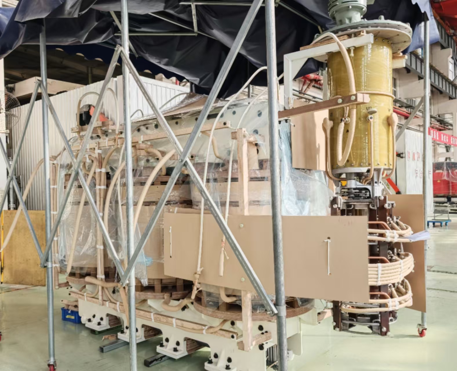
1. Transformer Core
The core of a transformer is made of high-grade steel laminated sheets, which provide a low-resistance path for the magnetic flux created when current passes through the windings. The core plays a critical role in the transformer’s efficiency by helping to reduce energy losses.
- Purpose: Conducts the magnetic field between the primary and secondary windings.
- Material: Typically made from silicon steel, which has high magnetic permeability to maximize efficiency.
- Design: The core is usually built with laminated sheets to minimize eddy current losses.
2. Windings
The windings are the coils of wire wrapped around the core. There are typically two windings in a power transformer:
- Primary winding: The coil that receives the electrical power from the source (high voltage side).
- Secondary winding: The coil that delivers the electrical power to the load (low voltage side).
The material of the windings is typically copper or aluminum, with copper being the more common material for its higher electrical conductivity. Windings are carefully designed to handle high current and voltage levels.
- Purpose: The windings create a magnetic field when electrical current passes through them. The voltage is transformed through electromagnetic induction between the windings.
- Design: The windings are typically wound onto a cylinder made of insulated copper or aluminum wire.
3. Tap Changer
A tap changer is a critical component used to adjust the voltage ratio of the transformer. It provides the ability to regulate voltage by changing the number of active turns on the winding. Tap changers are either:
-
On-load tap changers (OLTC) – Used for voltage regulation during operation without interrupting the supply.
-
Off-load tap changers – Used for voltage adjustments during maintenance.
-
Purpose: To adjust the voltage levels for fluctuations in load or to maintain a stable voltage output.
-
Design: It typically consists of a mechanical or electrical device that adjusts the taps on the windings.
4. Bushings
Bushings are insulating devices that allow electrical conductors to enter and exit the transformer safely. They are typically mounted on the transformer tank and serve as pass-throughs for the high-voltage connections.
- Purpose: To isolate the electrical components from the external environment and prevent accidental electrical shocks.
- Material: Often made from porcelain or polymer, which are excellent insulators.
5. Transformer Tank
The tank of a power transformer is the outer casing that houses the transformer’s internal components. It’s typically made of steel and filled with transformer oil (discussed further below). The tank provides mechanical protection for internal components and helps in heat dissipation.
- Purpose: To house and protect the transformer’s internal components, ensuring that they remain in a controlled, secure environment.
- Design: The tank is usually sealed to prevent contaminants from entering, but it also contains a conservator to accommodate oil expansion.
6. Transformer Oil
Transformer oil serves a dual purpose:
- It acts as an insulating material that helps in preventing electrical arcing.
- It also provides cooling by dissipating heat generated during operation.
The oil is usually stored in a separate tank called the conservator, which accommodates oil expansion and contraction due to temperature changes.
- Purpose: Insulates and cools the transformer.
- Types: Mineral oil is common, though synthetic oils or vegetable oils may be used in some modern designs for better environmental properties.
7. Conservator Tank
The conservator is a tank connected to the transformer tank and is used to store additional transformer oil. It ensures that the oil inside the transformer remains at an optimal level, even with temperature fluctuations that cause oil expansion.
- Purpose: Provides space for transformer oil expansion and contraction as the transformer heats up and cools down.
- Design: Connected to the transformer tank with a pipe, often fitted with a breather to prevent contamination.
8. Radiators and Fans
To ensure that the transformer operates at a safe temperature, radiators and fans are used to dissipate the heat generated by the electrical processes inside the transformer. These components help maintain an optimal temperature range, ensuring efficient transformer operation.
- Purpose: To cool the transformer and prevent overheating.
- Design: Radiators are typically mounted on the sides of the transformer tank, while fans can be installed for active cooling in larger transformers.
9. Grounding and Safety Components
In a power transformer, grounding is critical for safety. A grounding system is used to direct any fault current safely to the earth, preventing damage to equipment or injury to personnel.
- Purpose: Ensures safety during faults and keeps the transformer at a safe voltage level.
- Design: Consists of a grounding bus and safety relays to detect and isolate faults quickly.
10. Monitoring and Protection Devices
Modern transformers are equipped with a variety of sensors and protection devices to monitor their health and ensure safe operation. These include:
-
Pressure relief devices to release gases in case of internal faults.
-
Temperature sensors to prevent overheating.
-
Gas detection sensors to detect faults such as dielectric breakdown.
-
Purpose: To monitor the transformer's operation and detect early signs of failure.
-
Design: Sensors and alarms are integrated into the system, and protection relays are used to disconnect the transformer if a fault occurs.
Summary Table of Key Transformer Components
| Component | Purpose | Design Materials |
|---|---|---|
| Core | Conducts magnetic field | Silicon steel laminations |
| Windings | Create electromagnetic induction | Copper or aluminum wire |
| Tap Changer | Regulates voltage levels | Mechanical or electrical |
| Bushings | Insulate and provide entry for conductors | Porcelain or polymer |
| Tank | Houses and protects components | Steel |
| Transformer Oil | Insulates and cools the transformer | Mineral oil or synthetic oil |
| Conservator Tank | Stores additional oil for temperature changes | Steel |
| Radiators/Fans | Dissipate heat | Metal radiators, fans |
| Grounding System | Ensures safety during faults | Grounding bus, relays |
| Protection Devices | Monitor and protect against faults | Sensors, relays, alarms |
How Large Are Power Transformers Generally?
Power transformers vary significantly in size depending on their application, voltage rating, and power capacity. From compact units mounted on poles to massive ground-based giants weighing hundreds of tons, the physical size of a power transformer reflects its electrical performance requirements. Choosing the right size impacts installation, transportation, cooling, maintenance—and ultimately, grid reliability.
Power transformers generally range from small distribution units weighing a few hundred kilograms and measuring under a meter tall, to ultra-high voltage (UHV) transmission transformers exceeding 400 tons and standing over 5 meters high. The size is directly related to the transformer's voltage level, power rating (kVA or MVA), insulation requirements, and cooling system.
In this article, we explore the typical physical sizes of various types of power transformers, factors influencing their dimensions, and real-world examples for perspective.
Power transformer size varies widely based on capacity, voltage level, and cooling system.True
Small distribution transformers may be compact and pole-mounted, while large substation transformers require heavy-duty transport and specialized installation.
All power transformers are approximately the same size regardless of application.False
Transformers range in size from compact 25 kVA units to massive 1000+ MVA grid-scale transformers.
1. Size by Transformer Type and Voltage Level
| Transformer Type | Typical Power Rating (kVA/MVA) | Approx. Dimensions (L×W×H) | Weight Range |
|---|---|---|---|
| Pole-mounted distribution | 10–250 kVA | 0.5 × 0.5 × 0.7 m | 100–400 kg |
| Pad-mounted distribution | 100–2,500 kVA | 1.2 × 1.0 × 1.5 m | 0.6–2.5 tons |
| Substation transformer | 5–100 MVA | 3 × 2 × 3 m | 20–100 tons |
| Power plant unit transformer | 100–500 MVA | 5 × 4 × 5 m | 100–300 tons |
| UHV transmission transformer | 500–1,200 MVA | 8 × 6 × 6 m | 300–500+ tons |
The size of a transformer scales exponentially with voltage and power rating due to larger insulation clearances and cooling demands.
2. Factors That Influence Transformer Size
| Factor | How It Affects Size |
|---|---|
| Voltage Rating (kV) | Higher voltage = larger insulation clearance |
| Power Capacity (kVA/MVA) | More copper/iron and oil needed = heavier structure |
| Cooling Method | Air-cooled (AN/AF) is smaller than oil-cooled (ONAN/ONAF) |
| Frequency | Lower frequency (e.g., 50 Hz) needs larger cores |
| Insulation Type | Higher-class insulation reduces compactness |
For example, a 250 kVA pad-mounted transformer is roughly the size of a refrigerator, while a 1000 MVA grid transformer may be the size of a shipping container.
3. Volume and Footprint Requirements
| Application Area | Transformer Class | Site Space Needed (Typical) |
|---|---|---|
| Urban distribution | Compact or pad-mounted | < 3 m² (including enclosure) |
| Industrial substation | Ground-mounted oil units | 20–50 m² (foundation, tank, cooling) |
| High-voltage substation | Large 220–500 kV class | 100+ m² (including fencing, radiators) |
Large transformers require clearance zones, cooling space, and reinforced pads for operation and safety.
4. Real-World Examples
| Transformer Application | Voltage/Power Level | Approximate Size & Weight |
|---|---|---|
| Residential pole-mounted | 11 kV / 100 kVA | \~0.6 m tall, \~200 kg |
| Urban pad transformer (utility) | 33 kV / 2.5 MVA | \~1.5 m tall, \~2.5 tons |
| Substation (steel mill) | 132 kV / 40 MVA | \~3.5 m tall, \~65 tons |
| Thermal power plant step-up | 400 kV / 500 MVA | \~5.5 m tall, \~250 tons |
| National grid UHV substation | 765 kV / 1000 MVA | \~6–7 m tall, \~400–500 tons |
Transporting UHV transformers often requires multi-axle hydraulic trailers and special road permits.
5. Cooling System Impact on Size
| Cooling Type | Abbreviation | Volume & Weight Impact |
|---|---|---|
| Air Natural | AN | Smallest—used in dry-type |
| Oil Natural Air Natural | ONAN | Moderate—needs tank and radiators |
| Oil Forced Air Forced | ONAF | Larger—requires fans and oil pumps |
| Oil Forced Water Forced | OFWF | Largest—requires heat exchanger loop |
More cooling = more size, noise, and mechanical complexity, especially in high-duty cycles.
Summary Table: Transformer Size by Classification
| Class | Size Range | Use Case |
|---|---|---|
| Small (0.5–1.5 m) | 10–250 kVA | Street-level distribution |
| Medium (1.5–3.5 m) | 500 kVA–20 MVA | Industrial, municipal substations |
| Large (3.5–6.0 m) | 50–300 MVA | Utility-grade grid transformers |
| Extra-Large (6.0+ m) | 500–1200+ MVA | National grid or generation station |
What Does the Exterior of an Oil-Immersed Transformer Look Like?
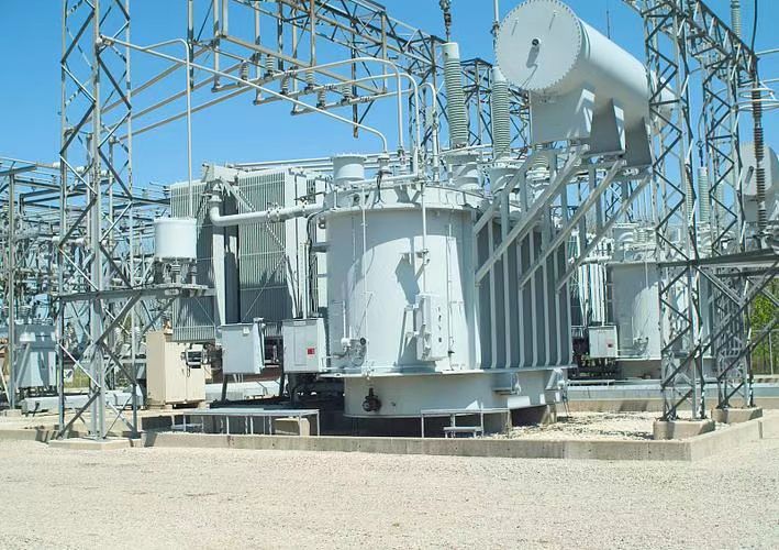
When you see a transformer sitting in a substation or an industrial yard, chances are it’s an oil-immersed transformer. These transformers use insulating oil to manage heat and electrical insulation. While their internal components do all the electrical work, the exterior features play a vital role in protection, cooling, connection, and maintenance. Recognizing these features helps engineers, operators, and technicians understand functionality, ensure safety, and plan installation or inspections.
The exterior of an oil-immersed transformer typically includes a sealed steel tank filled with insulating oil, high-voltage and low-voltage bushings for power connections, cooling systems such as radiators or corrugated fins, a conservator tank for oil expansion, protective devices like pressure relief valves and silica gel breathers, grounding terminals, and access panels for maintenance.
This article explores the visual structure, key external parts, and practical significance of the exterior design of oil-immersed power transformers.
Oil-immersed transformer exteriors include bushings, conservators, radiators, and protective devices essential for operation and safety.True
These parts manage heat, pressure, electrical connection, and environmental protection.
The external casing of an oil-immersed transformer serves no purpose beyond covering internal components.False
The exterior provides structural support, cooling, electrical interface, and safety protection.
1. Main Tank
| Feature | Description |
|---|---|
| Structure | Rectangular steel enclosure |
| Function | Houses the core, windings, and insulating oil |
| Design Elements | Welded or bolted steel, painted for corrosion resistance |
This is the central body of the transformer, designed to handle mechanical stress and oil pressure.
2. Cooling System: Radiators or Corrugated Panels
| Type | Appearance | Purpose |
|---|---|---|
| Radiators | Vertical steel tubes or panels attached to tank | Increases surface area for heat dissipation |
| Corrugated fins | Rippled steel sides of the main tank | Compact alternative to radiators |
| Fans (optional) | Attached below radiators in larger units | Enhance forced air cooling |
These components help maintain safe operating temperature and prevent overheating.
3. Bushings (HV and LV Terminals)
| Type | Location | Function |
|---|---|---|
| High-voltage bushings | Top or side-mounted | Bring in power at high voltage (e.g., 11 kV, 33 kV) |
| Low-voltage bushings | Top or opposite side | Deliver stepped-down voltage (e.g., 400 V) |
| Neutral bushing | Near LV terminals | Provides grounding or neutral connection |
Made of porcelain or polymer, these bushings safely isolate conductors from the metal tank.
4. Conservator Tank (Oil Expansion Chamber)
| Feature | Description |
|---|---|
| Shape | Cylindrical, mounted on top or offset |
| Function | Holds expanding oil as temperature rises |
| Connection | Linked to main tank via pipe |
Contains a rubber bladder or air-oil interface to manage oil volume changes.
5. Breather and Silica Gel Chamber
| Feature | Location | Purpose |
|---|---|---|
| Breather unit | Attached to conservator pipe | Filters moisture from air entering the tank |
| Silica gel chamber | Transparent canister | Absorbs moisture, changes color when saturated |
Maintains dry air in contact with transformer oil, extending insulation life.
6. Oil Level Indicator and Temperature Gauge
| Instrument | Function |
|---|---|
| Oil level sight glass | Visual scale showing oil height |
| Top oil thermometer | Measures oil temperature in main tank |
| WTI/OTI indicators | Winding and oil temperature instruments |
These instruments provide critical monitoring for safety and diagnostics.
7. Pressure Relief and Protection Devices
| Component | Function |
|---|---|
| Pressure relief valve | Vents pressure if internal gas builds up |
| Buchholz relay (for larger units) | Detects gas in the oil, signals internal fault |
| Gas sampling port | Allows analysis of dissolved gases (DGA) |
Ensures safe venting and fault detection before major damage occurs.
8. Drain Valves, Lifting Lugs, and Nameplate
| Feature | Purpose |
|---|---|
| Drain valve | For oil removal during servicing |
| Lifting lugs | Heavy-duty hooks for crane transport |
| Rating nameplate | Displays transformer specs (kVA, voltage, serial no.) |
These are essential for maintenance, transport, and regulatory compliance.
Summary Table: Key External Components of Oil-Immersed Transformers
| Component | Purpose | Appearance |
|---|---|---|
| Main tank | Houses internal elements, filled with oil | Large, boxy steel structure |
| Radiators/Fins | Dissipate heat | Corrugated or attached vertical panels |
| Bushings | Connect HV/LV terminals | Tall porcelain or polymer insulators |
| Conservator | Handles oil expansion | Cylindrical tank above main body |
| Breather | Removes moisture | Tube with silica gel chamber |
| Temperature/Oil gauges | Monitor safety thresholds | Dial meters or digital sensors |
| Pressure relief valve | Prevents explosion under gas pressure | Valve or dome on top or side |
| Drain/valves | Maintenance ports | Brass or steel taps near bottom |
| Nameplate | Lists specs for identification | Metal plate with engraved data |
How Do Dry-Type Transformers Differ in Appearance?
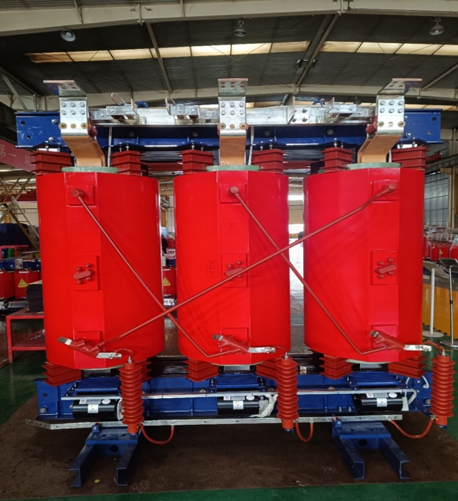
Unlike their oil-immersed counterparts, which are sealed in tanks filled with insulating liquid, dry-type transformers operate entirely in the air. This fundamental design difference drastically changes their external appearance, cooling configuration, and enclosure type. If you’ve ever walked into an industrial building or commercial electrical room, chances are you’ve seen one without even realizing it.
Dry-type transformers differ in appearance from oil-immersed transformers through their open or enclosed air-cooled design, visible cast resin or varnished windings, absence of oil tanks, and lighter, more compact construction. They often feature ventilated steel enclosures, mounted skids or frames, and clearly visible temperature sensors or terminal blocks.
This article explores what distinguishes dry-type transformers visually and structurally, why their design is suitable for certain environments, and how they can be identified in the field.
Dry-type transformers are air-cooled units with visible coils and no oil tank.True
They use natural or forced air for cooling and are designed for safe indoor environments without risk of oil leakage.
Dry-type transformers look the same as oil-immersed transformers.False
Their construction, cooling, and enclosure are different, making them visually distinct and safer for specific settings.
1. Open or Ventilated Construction
| Feature | Dry-Type Transformer | Oil-Immersed Transformer |
|---|---|---|
| Cooling medium | Air | Oil |
| Outer design | Open coils or steel enclosure with louvers | Sealed steel tank |
| Visible components | Windings, core, terminals | Only external tank, bushings, radiators |
Dry-types often have ventilation slots or grills, and you can see internal windings through the casing.
2. Visible Resin-Coated or Varnished Windings
| Winding Encapsulation | Appearance | Purpose |
|---|---|---|
| Cast resin (CRT) | Red or brown epoxy block-like coils | Protects against dust, moisture, arc |
| Vacuum Pressure Impregnated (VPI) | Glossy windings coated in varnish | Moderate protection with airflow |
The distinct red epoxy cast or shiny varnished coils are a signature look of dry-type transformers.
3. No Radiators or Conservator Tanks
| System Element | Presence in Dry-Type Transformers |
|---|---|
| Oil expansion conservator | ❌ Not present |
| Cooling fins or radiators | ❌ Not needed |
| Air ducts or fans | ✅ Used for forced air cooling in large units |
The lack of fluid containment structures makes dry-types appear more compact and less industrial.
4. Enclosures and Mounting
| Enclosure Type | Use Case | Appearance |
|---|---|---|
| Open type | Clean, dry indoor settings | Core and coils exposed or partially shielded |
| NEMA 1/2/3R/12 enclosures | Industrial/commercial applications | Steel box with louvered ventilation |
| IP-rated cabinets | Outdoor or dusty areas | Fully sealed with cooling channels |
Dry-type transformers are often floor-mounted on skids or beams, designed for easy indoor installation.
5. Terminal Arrangement and Markings
| Connection Design | Description |
|---|---|
| Terminal blocks | Clearly marked input/output phases |
| Color-coded cables | L1/L2/L3 with ground and neutral |
| Temperature probes or RTDs | External wires for monitoring coil temps |
Connections are typically more accessible and visible than in oil-filled units, which are hidden under sealed covers.
6. Common Dimensions and Weight
| Rating Range | Approximate Size | Weight Estimate |
|---|---|---|
| 100–250 kVA | 1.0 × 0.8 × 1.2 m | 500–1,000 kg |
| 500–1,000 kVA | 1.5 × 1.2 × 1.8 m | 1.2–3.0 tons |
| 1–5 MVA | 2.5 × 2.0 × 2.5 m | 4–8 tons |
Dry-type units are generally lighter and smaller than oil-immersed ones of the same rating—ideal for indoor and fire-sensitive zones.
Summary Table: Appearance Differences of Dry-Type vs. Oil-Immersed Transformers
| Feature | Dry-Type Transformer | Oil-Immersed Transformer |
|---|---|---|
| Cooling system | Air-cooled with ventilation | Oil-cooled with tank, radiators |
| Enclosure type | Open or vented metal cabinet | Sealed steel tank |
| Visible components | Coils, core, terminals often visible | Bushings, conservator, radiators externally seen |
| Size and weight | More compact for same rating | Heavier due to oil, tank, and larger clearances |
| Common use environment | Indoors, commercial, fire-sensitive areas | Outdoors, substations, heavy-duty applications |
What Are the Visual Indicators of a Transformer’s Voltage Rating?
Whether in a substation or mounted on a utility pole, transformers often provide visual clues about their voltage rating—if you know what to look for. This information is vital for field engineers, utility workers, and maintenance personnel who must verify system compatibility, inspect equipment, or conduct troubleshooting. Misidentifying voltage levels can lead to hazards, failures, or serious code violations.
The visual indicators of a transformer’s voltage rating include the size and type of bushings, the number of insulator sheds, physical clearances, high-voltage warning labels, color coding, cable thickness, and the nameplate which explicitly states the rated primary and secondary voltages. These visual cues help identify if a transformer is designed for low, medium, or high-voltage applications.
In this article, we explain how to visually assess a transformer’s voltage class based on physical appearance, components, and markings, helping ensure safety and compatibility in field operations.
Transformers show their voltage rating through visual elements like bushing size, insulators, clearance, and nameplate data.True
These features help technicians and engineers identify voltage levels without testing or opening the unit.
There is no way to visually determine the voltage rating of a transformer.False
Several design features such as insulator configuration and physical size directly correspond to voltage class.
1. Size and Design of Bushings
| Voltage Level | Bushing Characteristics |
|---|---|
| Low Voltage (<1 kV) | Small bushings, sometimes cable-style, often enclosed |
| Medium Voltage (1–36 kV) | Medium-sized, porcelain or polymer insulators, 3–5 sheds |
| High Voltage (66–400+ kV) | Large, tall bushings with 8–20 sheds and oil-sealed design |
The bigger and more complex the bushing, the higher the insulation level—and thus the higher the voltage.
2. Number and Shape of Insulator Sheds (Creepage Path)
| Voltage Class | Insulator Appearance |
|---|---|
| Low (<1 kV) | Minimal or no sheds, compact design |
| Medium (11–33 kV) | 3–5 sheds, stacked rib design |
| High (66+ kV) | Tall insulators with 8+ large, widely spaced sheds |
More insulator sheds = longer creepage path = higher voltage capability.
3. Physical Size and Spacing
| Indicator | Observation |
|---|---|
| Larger tanks | Higher voltage = larger clearances = bigger tank |
| Bushing spacing | HV terminals spaced further apart to avoid arcing |
| Ground clearance | Mounted higher or isolated for HV safety |
A small pad-mounted transformer usually serves 400/230V; a large ground-mounted substation unit could be rated for 132 kV or more.
4. High-Voltage Warning Labels and Signage
| Label Type | Voltage Indicator |
|---|---|
| “DANGER 11,000 VOLTS” | Medium-voltage transformer (11 kV) |
| “DANGER 33/66/132/220/400 kV” | High-voltage grid transformer |
| Language and color | Typically red, white, and yellow with voltage symbols |
These are legally required safety signs and a direct clue to voltage class.
5. Cable Thickness and Connector Size
| Voltage Level | Cable Characteristics |
|---|---|
| Low voltage | PVC cables, thin conduit |
| Medium voltage | XLPE-insulated, \~30–60 mm diameter |
| High voltage | Armored cables or overhead bared conductors, very thick |
Thicker cables mean higher voltage or current, though current load must also be considered.
6. Color Coding and Terminal Labeling
| Voltage Side | Common Colors/Markings (Region Dependent) |
|---|---|
| HV Side | Red, Orange, “H1/H2/H3” labels |
| LV Side | Black, Blue, “X1/X2/X3” or “L1/L2/L3” |
| Ground/Neutral | Green, Yellow-Green, or “N” |
Many transformers follow IEC, ANSI, or regional color standards for quick field identification.
7. Nameplate Specifications
| Field on Nameplate | Typical Information Shown |
|---|---|
| Rated primary voltage | E.g., 11,000 V, 33,000 V, 400,000 V |
| Rated secondary voltage | E.g., 400 V, 11 kV, 132 kV |
| Phase configuration | Delta, Wye (Dyn11, YNd1, etc.) |
| Frequency and kVA/MVA | E.g., 50 Hz, 1000 kVA |
The nameplate is the most definitive indicator of voltage rating and should be read during inspection.
Summary Table: Visual Voltage Rating Indicators
| Visual Indicator | Low Voltage (<1 kV) | Medium Voltage (1–36 kV) | High Voltage (66+ kV) |
|---|---|---|---|
| Bushing size | Small, enclosed | Porcelain/polymer, 3–5 sheds | Tall, oil-filled, 8+ sheds |
| Tank size | Compact | Medium | Very large with radiators |
| Cable thickness | Thin | Moderate | Thick armored cables or busbars |
| Clearance spacing | Minimal | Increased | Wide spacing for air insulation |
| Signage | "400V" or none | "DANGER 11,000V" | "DANGER 132/220/400 kV" signs |
| Nameplate voltages | 230/400 V | 11–33 kV | 66–400+ kV |
Where Can You Typically See Power Transformers?
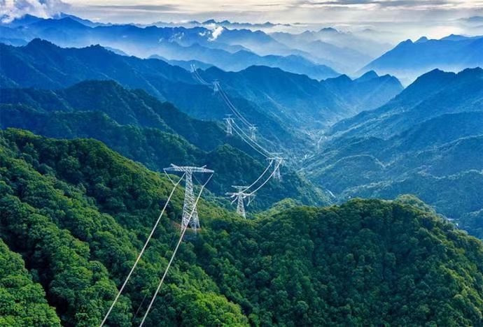
Power transformers may seem like hidden giants of the electrical world, but they’re all around us—in plain sight and behind the scenes—serving as the backbone of modern power systems. While you may not always notice them, their presence is essential in converting and delivering electricity safely and efficiently across diverse environments.
You can typically see power transformers in power generation plants, high-voltage transmission substations, distribution substations in cities and rural areas, industrial facilities, commercial complexes, residential neighborhoods, and renewable energy installations such as wind and solar farms. Each location requires voltage transformation and system reliability provided by these transformers.
This article highlights common real-world locations where power transformers are found, why they are used there, and how to recognize them based on physical form and function.
Power transformers are widely visible at power stations, substations, industrial zones, and even residential streets.True
They play key roles in voltage transformation across all stages of electricity delivery, from generation to consumption.
Power transformers are only found inside power plants and are not visible elsewhere.False
They are used across the electrical network, including outside plants, in substations, and in public or industrial spaces.
1. Power Generation Stations (Thermal, Hydro, Nuclear, and Gas)
| Location | Transformer Function | Visual Indicator |
|---|---|---|
| Inside generator switchyard | Step-up voltage to transmission level | Massive oil-immersed units, radiators |
| Auxiliary services | Feed internal systems at lower voltages | Smaller dry-type or oil-cooled units |
Transformers here are among the largest in the grid, stepping up from 11–25 kV to 220–765 kV.
2. High-Voltage Transmission Substations
| Location | Transformer Purpose | Voltage Levels |
|---|---|---|
| Grid substations | Interface between regions | 400 kV, 220 kV, 132 kV |
| Interconnecting substations | Link between utilities or countries | Large three-phase transformers |
These are often fenced off, with tall bushings and extensive cooling systems, clearly visible in rural or semi-urban areas.
3. Urban and Rural Distribution Substations
| Site | Transformer Role | Example Sizes and Appearance |
|---|---|---|
| City substation | Step-down to 33/11 kV for city zones | Ground-mounted, large enclosure |
| Village/estate power huts | Deliver 400/230 V to homes/businesses | Compact pad-mounted or pole units |
These are some of the most frequently seen transformers, often behind fences or mounted on concrete platforms.
4. Industrial and Commercial Complexes
| Facility Type | Transformer Use | Voltage Range and Type |
|---|---|---|
| Manufacturing plants | Power for machinery and control panels | 11/6.6 kV to 415 V |
| Office towers, malls | HVAC, lighting, and UPS systems | 11 kV to 400/230 V dry-type transformers |
Transformers here may be found indoors or in utility rooms, often with vented enclosures or resin-coated windings.
5. Residential Areas and Neighborhoods
| Location | Purpose of Transformer | Common Type |
|---|---|---|
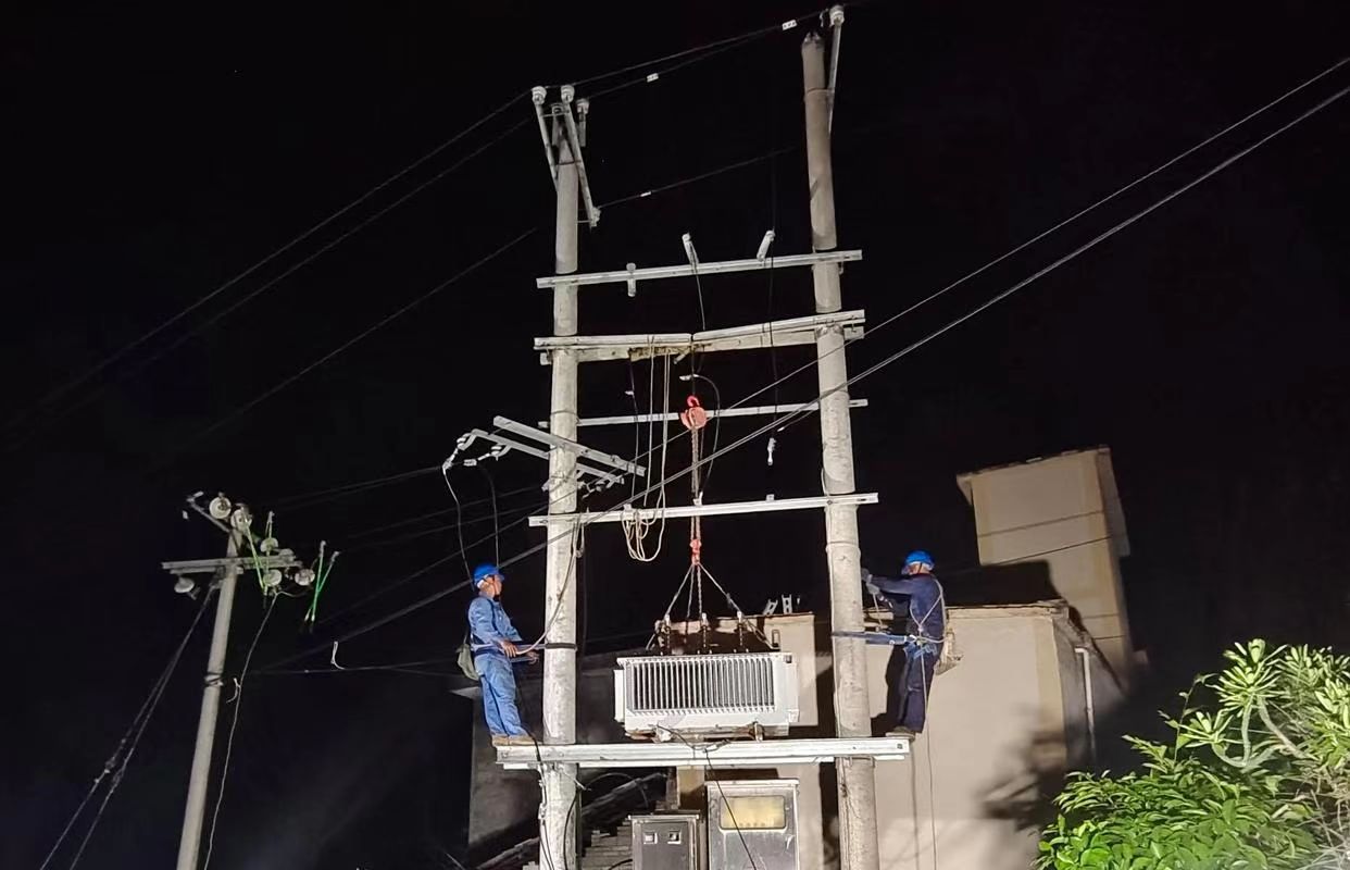
| Urban neighborhoods | Last voltage step for homes | Pole-mounted or pad-mounted |
| Apartments or gated colonies | Supply for multiple units from shared point | 11 kV → 400/230 V |
You can spot these on poles, sidewalks, or building basements, serving clusters of houses or blocks.
6. Renewable Energy Installations (Wind and Solar Farms)
| Site | Transformer Function | Placement and Type |
|---|---|---|
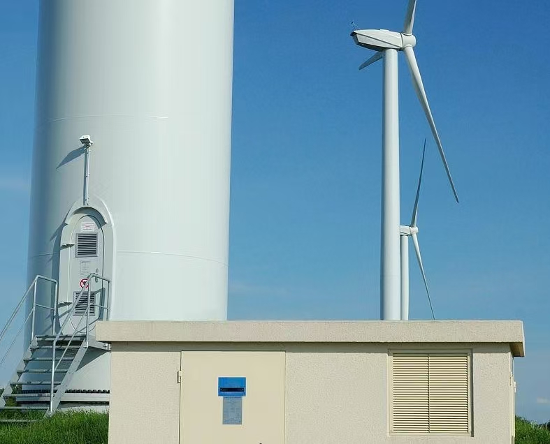
| Solar power stations | Step-up to 11–33 kV for collector grid | Pad-mounted or skid-mounted oil units |
| Wind turbine bases | Step-up from 690 V to medium voltage | Compact oil-immersed or dry types |
| Collector substations | Combine outputs from multiple turbines | Large outdoor power transformers |
These transformers make renewable sources grid-compatible, often located next to inverters or in shipping-container-like enclosures.
7. Transport Infrastructure (Airports, Railways, Ports)
| Sector | Application | Voltage Levels and Installation |
|---|---|---|
| Rail electrification | Step-down from grid to traction voltage | 132/66/33 kV → 25 kV |
| Airports and seaports | Lighting, baggage systems, backup power | 11 kV → 400/230 V |
These transformers are often found in subsurface utility areas or adjacent to control buildings.
Summary Table: Common Places to See Power Transformers
| Location Type | Transformer Use | Typical Voltage Conversion |
|---|---|---|
| Power Generation Plant | Step-up to transmission voltage | 11–25 kV → 220–765 kV |
| High-Voltage Substation | Regional power flow control | 400/220/132 kV ↔ grid distribution |
| Urban Distribution Substation | Step-down for local networks | 33/22/11 kV → 400/230 V |
| Industrial Facility | Plant equipment and automation supply | 6.6/11 kV → 415/230 V |
| Residential Block | Final distribution to homes | 11 kV → 230 V |
| Renewable Energy Site | Connect green energy to the grid | 690 V → 11/33 kV |
| Rail and Transport Hubs | Electrified tracks and operations | 132/33 kV → 25 kV or 400 V |
Conclusion
Power transformers come in various sizes and designs, but they all share key components like cores, windings, and cooling systems. From the large, oil-filled tanks with cooling fins to smaller, dry-type units enclosed in protective casings, their appearance reflects their role in safely and efficiently managing electrical voltage. Recognizing these features helps in understanding how transformers fit into the energy infrastructure around us.
FAQ
Q1: What does a typical power transformer look like?
A1: A power transformer is usually a large, rectangular, metal-clad unit with cooling fins, radiators, or oil tanks on the sides. It may have:
Bushings (cylindrical insulators) on the top for high-voltage connections
Cooling fans or oil pumps
A control cabinet for protection and monitoring equipment
A grounded frame and base pad for mounting
Depending on the size, it may sit on a concrete pad or within a substation enclosure.
Q2: What are the visible components of a power transformer?
A2: Key visible components include:
High-voltage bushings (ceramic or polymer insulators)
Low-voltage bushings
Cooling system (radiators, fans, oil conservator tank)
Tap changer mechanism (for voltage adjustment)
Protection relays and control panels
Nameplate indicating technical specifications
Q3: Do all power transformers look the same?
A3: No. Power transformers vary in design based on:
Voltage rating
Cooling method (oil-immersed vs. dry-type)
Indoor or outdoor installation
Phase configuration (single-phase vs. three-phase)
Larger utility transformers are bulkier with more visible components, while dry-type transformers may be enclosed in ventilated steel housings.
Q4: How can I identify a power transformer in a substation?
A4: In substations, power transformers are the largest units present. They are usually placed on graveled pads, connected by thick busbars or cables, and surrounded by protective fencing. The cooling fins, oil tanks, and high-voltage insulators make them easy to identify.
Q5: Can I see a power transformer in public places?
A5: Yes. Power transformers are visible in:
Electric substations
Behind industrial buildings
On utility poles (smaller ones)
Wind and solar power facilities
Larger units are fenced for safety, while smaller distribution types may be mounted on poles or inside metal boxes.
References
"Visual Guide to Power Transformers" – https://www.transformertech.com/what-power-transformer-looks-like – Transformer Tech
"What Does a Transformer Look Like?" – https://www.powermag.com/transformer-visual-components – Power Magazine
"Power Transformer External Components" – https://www.electrical4u.com/power-transformer-components – Electrical4U
"Transformer Design and Construction Overview" – https://www.researchgate.net/transformer-structure-guide – ResearchGate
"Transformer Identification and Layouts in Substations" – https://www.sciencedirect.com/power-transformer-configuration – ScienceDirect
"Smart Grid Visuals: Recognizing Grid Equipment" – https://www.smartgridnews.com/what-transformers-look-like – Smart Grid News
"Energy Central: Substation Transformer Basics" – https://www.energycentral.com/c/ee/transformer-layout-basics – Energy Central
"PowerGrid’s Visual Tour of Electrical Transformers" – https://www.powergrid.com/power-transformer-visual-guide – PowerGrid